
Pendulum striding exercise devices

a technology of exercise devices and exercise devices, applied in the field of exercise devices, can solve the problems of limiting the use of users' feet, affecting the fitness of users,

Active Publication Date: 2005-06-09
RODGERS JR ROBERT E
View PDF99 Cites 61 Cited by
  • Summary
  • Abstract
  • Description
  • Claims
  • Application Information

AI Technical Summary

Benefits of technology

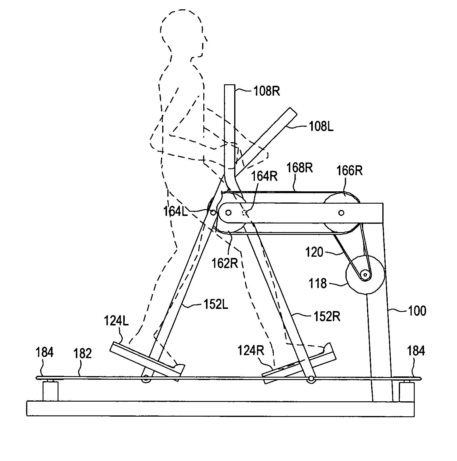
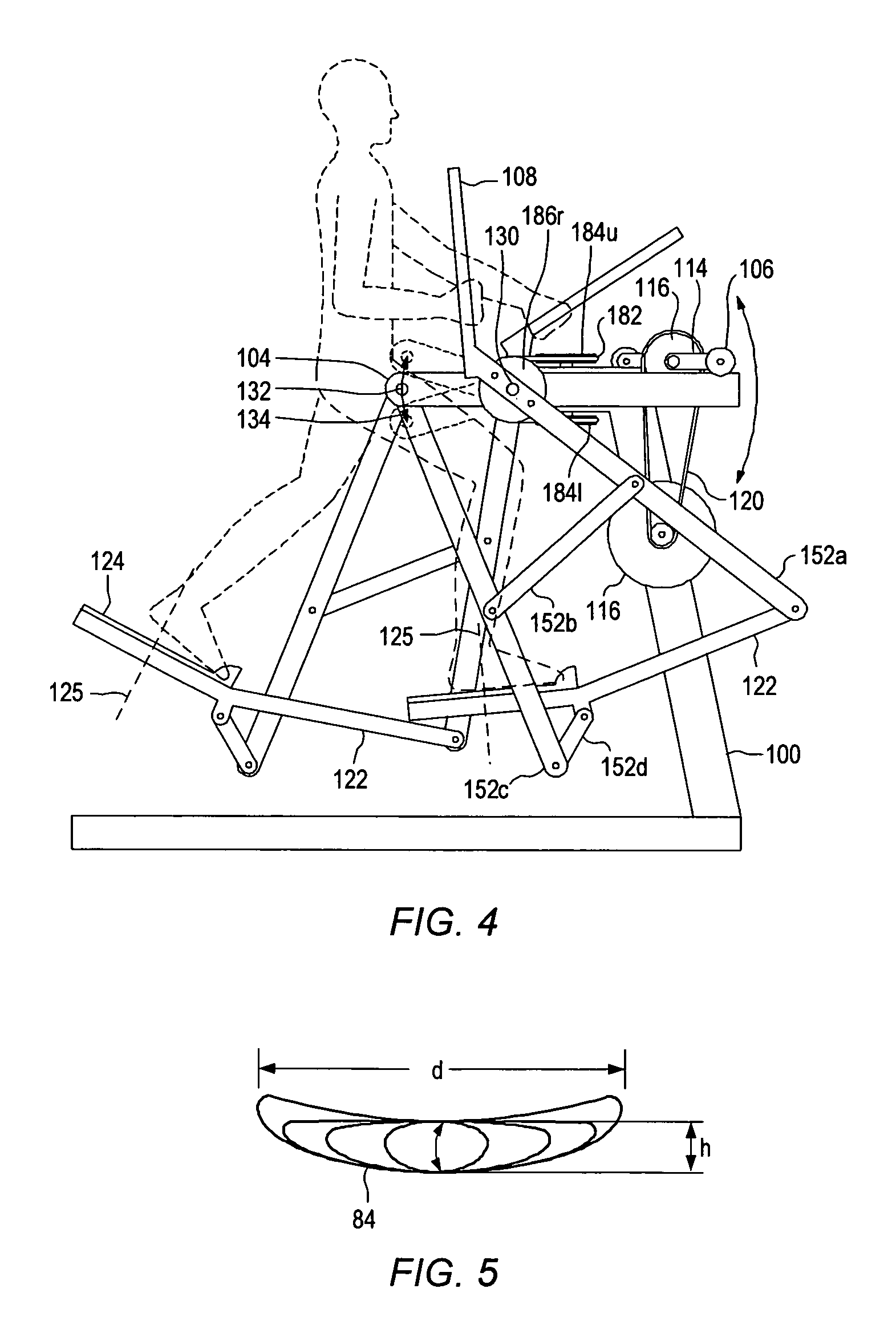
[0009] An exercise apparatus may include a frame. The frame may include at least a portion that remains substantially stationary during use. A crank system may be coupled to the frame. The crank system may include one or more crank members. A brake/inertia device may be coupled to the crank system. In certain embodiments, an exercise apparatus may include a pivotal linkage pendulum system. A pivotal linkage pendulum system may be coupled to the crank system. A pivotal linkage pendulum system may include one or mor

Problems solved by technology

For example, cross country ski machines may not allow a user to lift the front of his / her foot above a flat plane defined by the top of the pedal or footpad.
Elliptical machines may, however, constrain a user's foot to the mechanically defined elliptical path of the footpads or foot pedals.
The elliptical path may be too long for shorter users or too short for taller users.
Thus, an elliptical apparatus may not accommodate a variety of users.
In addition, a jogging stride is longer than a walking stride so a fixed stride length apparatus may not optimally simulate several different types of exercise activities.
Such motion may not accurately simulate a walking, striding, jogging, or climbing motion.
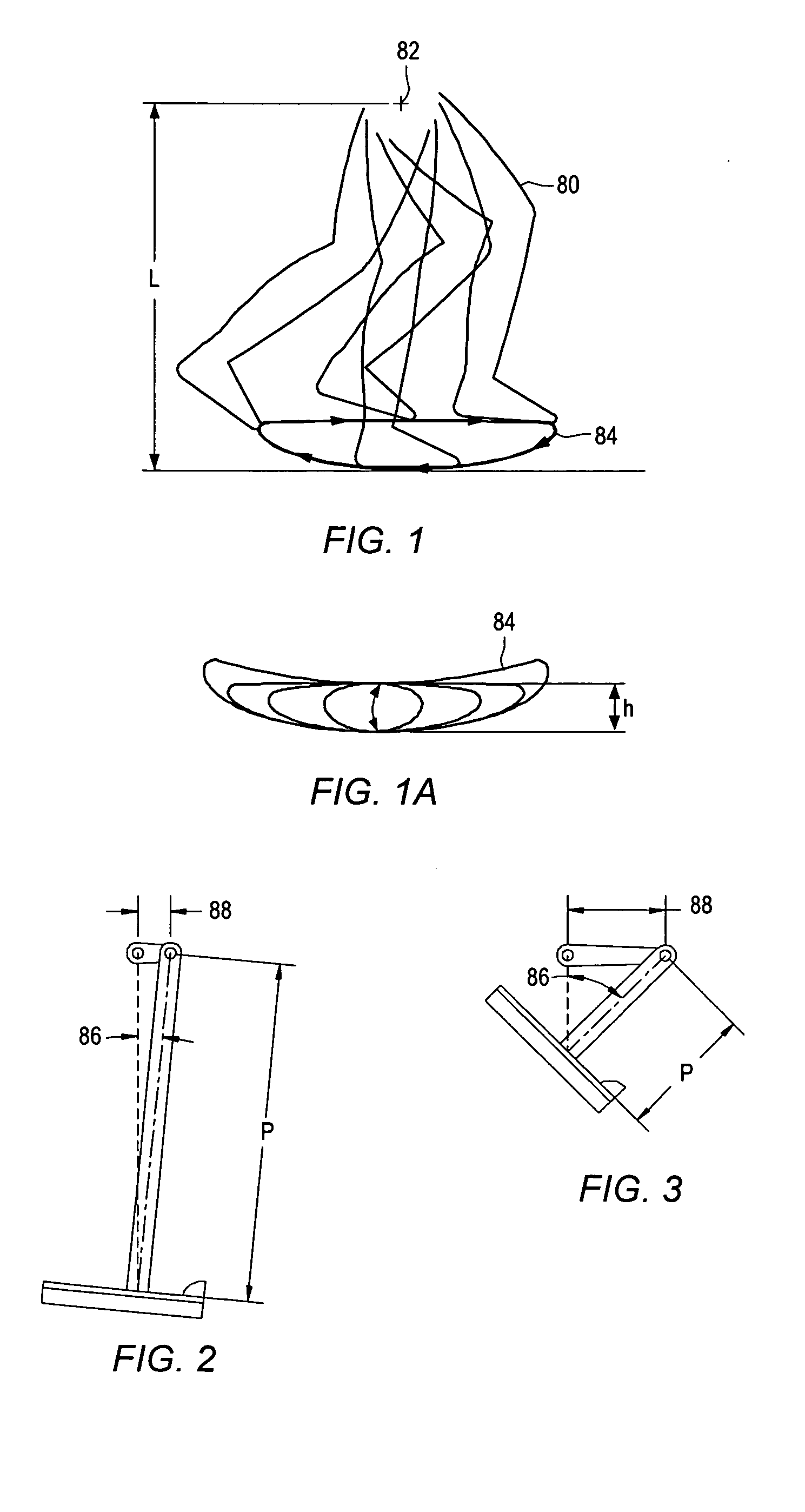
A fixed pendulum length may not allow for foot lift or vertical amplitude in the motion of the foot, and thus, may not provide naturally accommodating foot motion.
Other pendulum motion exercise apparatus may have relatively short pendulum lengths that may not properly accommodate the path of motion of the foot or legs of the human body.

Method used


Image

  • Pendulum striding exercise devices
  • Pendulum striding exercise devices
  • Pendulum striding exercise devices

Examples


Embodiment Construction

[0042] In the context of this patent, the term “coupled” means either a direct connection or an indirect connection (e.g., one or more intervening connections) between one or more objects or components. The phrase “directly attached” means a direct connection between objects or components. The term “support” means a first element, directly or indirectly, locates or positions a second element by pushing or pulling on the second element. The first element may be directly attached or coupled to the second element when providing support. The first element may be in compression while pushing or in tension while pulling on the second element.

[0043] The term “path” means any type of path that an object (e.g., a foot, a footpad, a link member, a movable member, or a coupling) or a point in space may undertake during motion. For example, a path may include a closed path or a back and forth path.

[0044] A “back and forth path of motion” means motion along a curved or straight line with two e...


PUM


Abstract

An exercise apparatus may include a frame. A crank system may be coupled to the frame. A brake / inertia device may be coupled to the crank system. A pivotal linkage pendulum system may be coupled to the crank system. The pivotal linkage pendulum system may include one or more link members. An upper pivot point of at least one of the link members may be coupled to the crank system. In some embodiments, the upper pivot point of the at least one of the link members may be coupled to the crank system through a movable member. The upper pivot point may move in a closed path motion. A foot member may be coupled to one or more of the link members. The foot member may include a footpad. A majority of a path of motion of the footpad may be below the closed path during use.

Description

PRIORITY CLAIM [0001] This application claims the benefit of U.S. Provisional Patent Application No. 60 / 526,802 entitled “Pendulum Striding Exercise Device” to Robert E. Rodgers, Jr., filed on Dec. 4, 2003; U.S. Provisional Patent Application No. 60 / 585,787 entitled “Pendulum Striding Exercise Device” to Robert E. Rodgers, Jr., filed on Jul. 6, 2004; and U.S. Provisional Patent Application No. 60 / 619,824 entitled “Pendulum Striding Exercise Device” to Robert E. Rodgers, Jr., filed on Oct. 18, 2004.BACKGROUND [0002] 1. Field of the Invention [0003] The present invention relates generally to an exercise apparatus. Certain embodiments relate to exercise apparatus that may allow exercise such as simulated walking, striding, jogging, and / or climbing. [0004] 2. Description of Related Art [0005] Exercise devices have been in use for years. Some typical exercise devices that simulate walking, jogging, or climbing include cross country ski machines, stair climbing machines, elliptical motion...

Claims


Application Information

Patent Timeline
IPC IPC(8): A63B22/04A63B22/06A63B69/16
CPCA63B21/225A63B22/001A63B22/0056A63B22/0664A63B2225/09A63B2022/0051A63B2022/0053A63B2022/067A63B2022/0017A63B22/0017
Inventor RODGERS, ROBERT E. JR.
Owner RODGERS JR ROBERT E
Learn More