Flow sensor signal conversion

Inactive Publication Date: 2005-06-16
BROOKS INSTRUMENT
View PDF8 Cites 32 Cited by
  • Summary
  • Abstract
  • Description
  • Claims
  • Application Information

AI Technical Summary

Benefits of technology

[0029] Various aspects of the present invention derive from Applicant's identification and appreciation of a correlation between fluid sensor output curves and a characteristic curve of a sensor when the sensor is modeled with a transfer function operating on f

Problems solved by technology

In practice, providing such a flow sensor is a difficult task.
Conventionally, it is not well understood how the sensor response curves vary from fluid to fluid.
This unpredictability makes it difficult to develop a flow sensor that

Method used


Image

  • Flow sensor signal conversion
  • Flow sensor signal conversion
  • Flow sensor signal conversion

Examples


Embodiment Construction

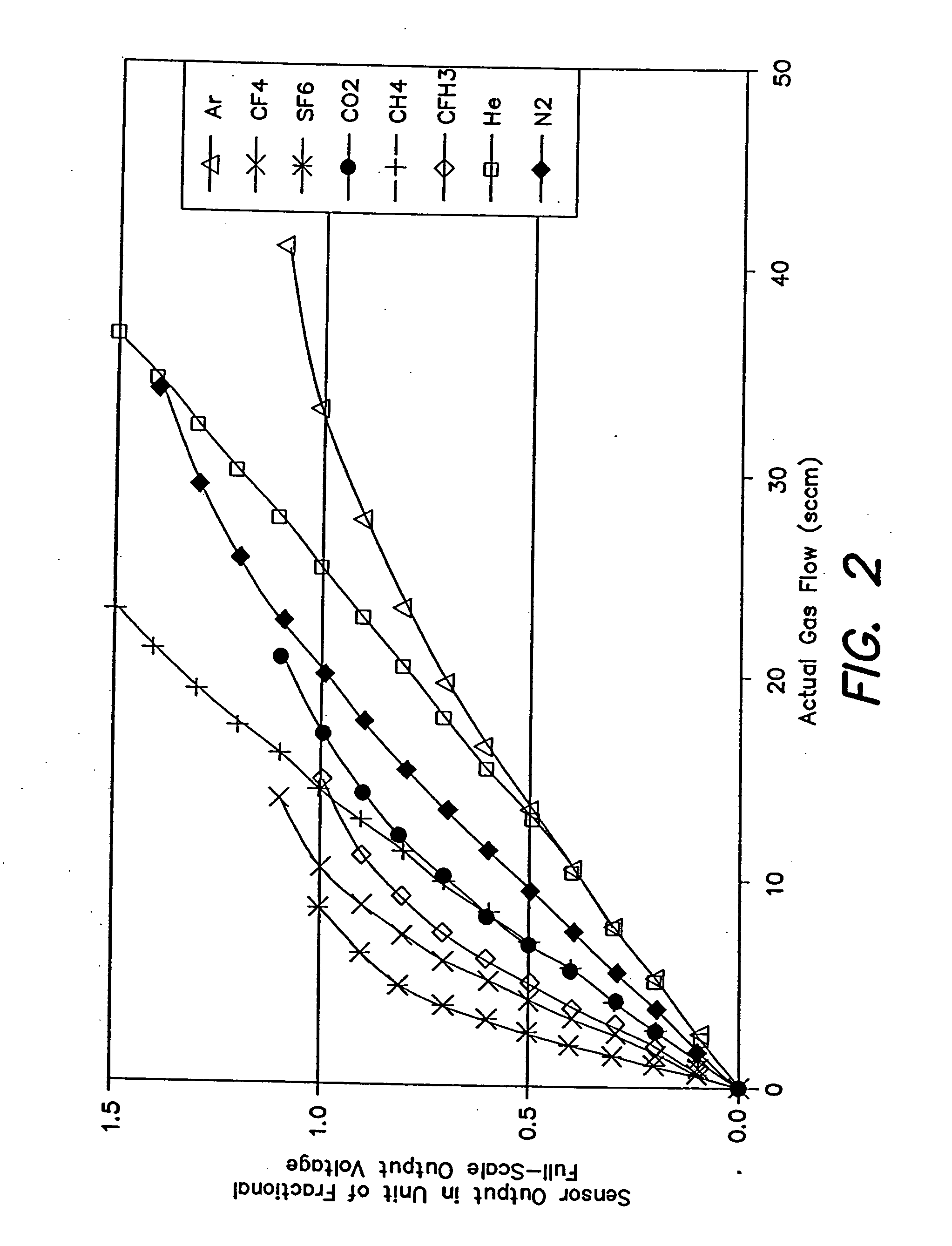
[0041] Methods have been proposed to address the difficulties that may result from variation in the behavior of a sensor when operating with different fluids. The variation may be influenced, in part, by the non-linear relationship between flow rate and sensor output. For example, restricting operation of the flow sensor to a linear range of a sensor response curve for a particular fluid may mitigate problems associated with the non-linearity of the sensor. As illustrated in FIG. 2, a sensor response curve for a particular fluid may have a portion that is approximately linear. By considering only flow rates within this limited range, sensor output values can be assumed to have an approximately linear, and thus predictable, relationship with the fluid flow.

[0042] However, a significant portion of a desired range of use of many of the sensor response curves lies outside the respective linear range and cannot be adequately approximated by a straight line. As such, limiting flow rates ...


PUM


Abstract

A method of obtaining at least one representation of a characteristic function of a sensor from a test fluid during calibration of the sensor according to a sensor model having a transfer function operating on flow rate, at least one sensor property and at least one fluid property and employing the at least one representation of the characteristic function to determine flow rates through the sensor during operation with an arbitrary fluid.

Description

CROSS-REFERENCE TO RELATED APPLICATION [0001] This application is a divisional application of and claims the benefit under 35 U.S.C. §120 to pending U.S. patent application Ser. No. 10 / 400,149, filed on Mar. 26, 2003, entitled “Flow Sensor Signal Conversion,” and bearing Attorney Docket No. U0128 / 700040, which is hereby incorporated by reference in its entirety.FIELD OF THE INVENTION [0002] This invention relates to the field of mass flow sensors and, more particularly, to methods and apparatus for providing flow signals that accurately indicate the actual fluid flow of arbitrary fluids through a flow path of a sensor across a wide range of flow rates. BACKGROUND OF THE INVENTION [0003] Mass flow sensors are used in a wide variety of applications to measure the mass flow rate of a gas or other fluid. One application in which a mass flow sensor may be used is a mass flow controller. In a conventional mass flow controller, the mass flow rate of a fluid flowing in a main flow path is r...

Claims


Application Information

Patent Timeline
IPC IPC(8): G01F1/684G01F1/696G01F5/00
CPCG01F1/6842G01F1/6847G01F1/6965G01F25/0007G01F15/024G01F15/046G01F5/00G01F25/10G01F1/00G01F1/696G01F25/00
Inventor WANG, CHIUNVALENTINE, WILLIAM S.LULL, JOHN M.
Owner BROOKS INSTRUMENT
Why Eureka
Try Eureka