

Disc cleaner
a technology for cleaning discs and cleaning cloths, applied in the field of cleaning discs, can solve the problems of linear wiped dust residue along the line, easy to miss the dust of cleaning cloths, and large accumulation of dus
- Summary
- Abstract
- Description
- Claims
- Application Information
AI Technical Summary
Benefits of technology
Problems solved by technology
Method used
Image

Examples
first embodiment
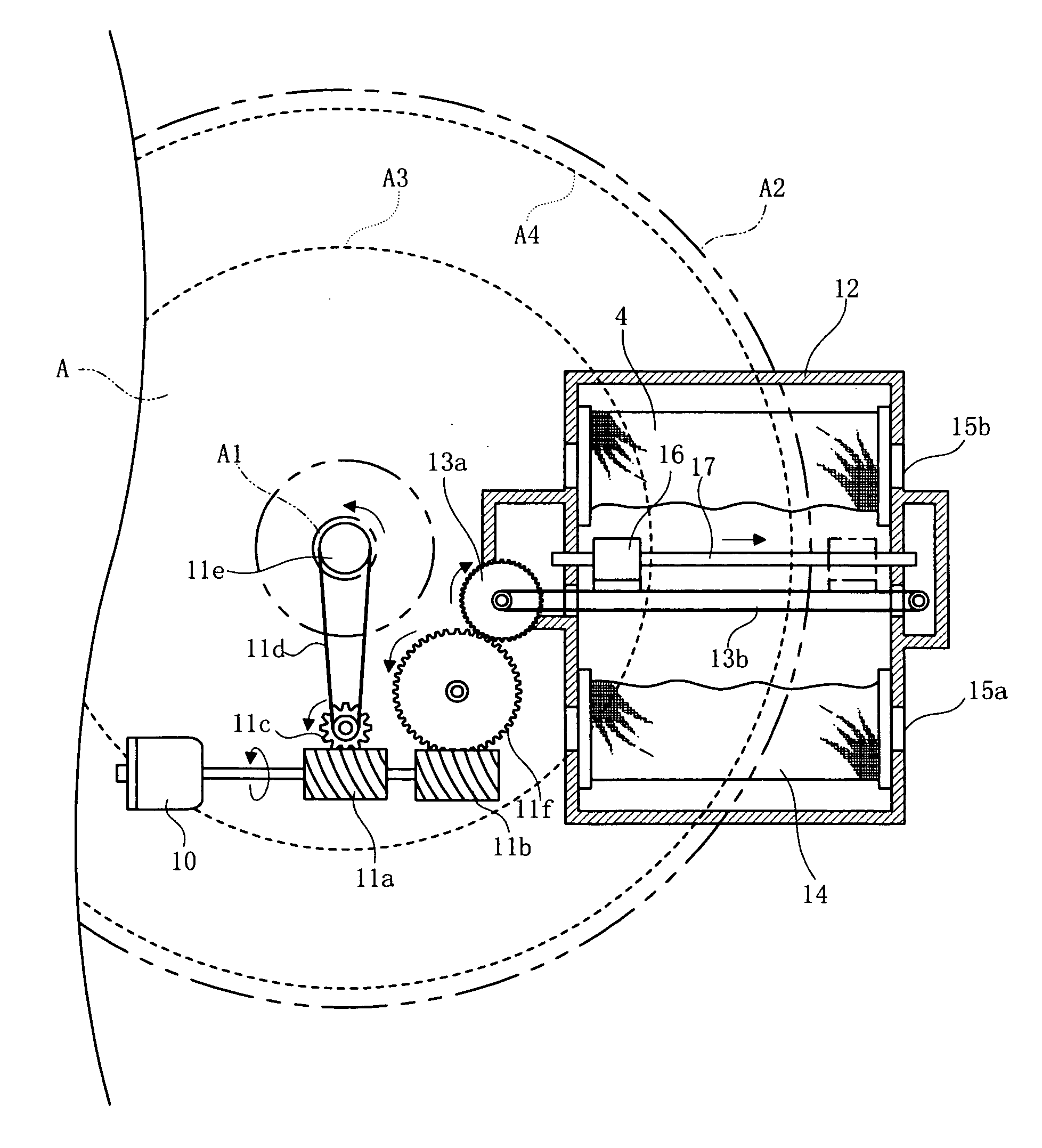
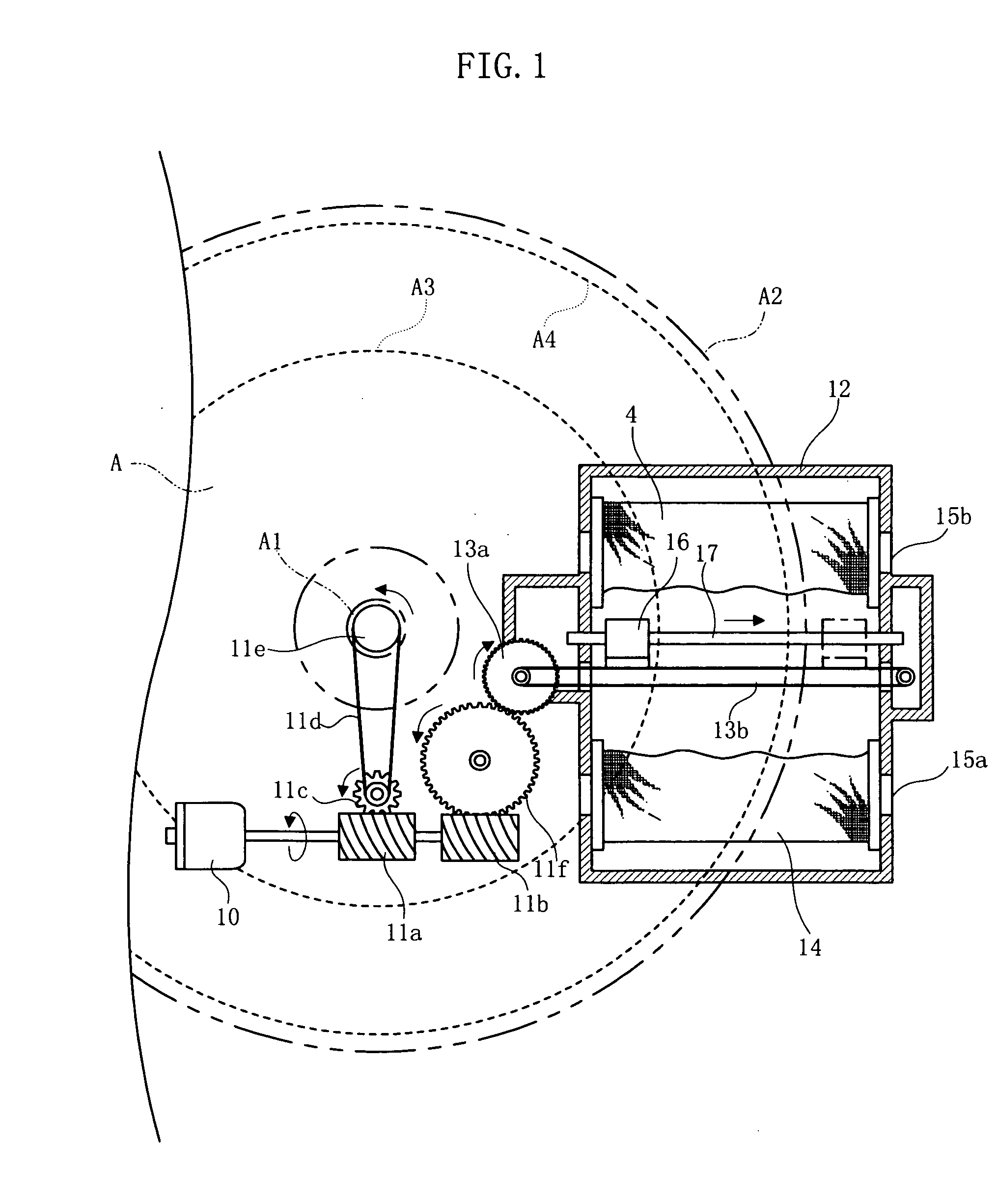
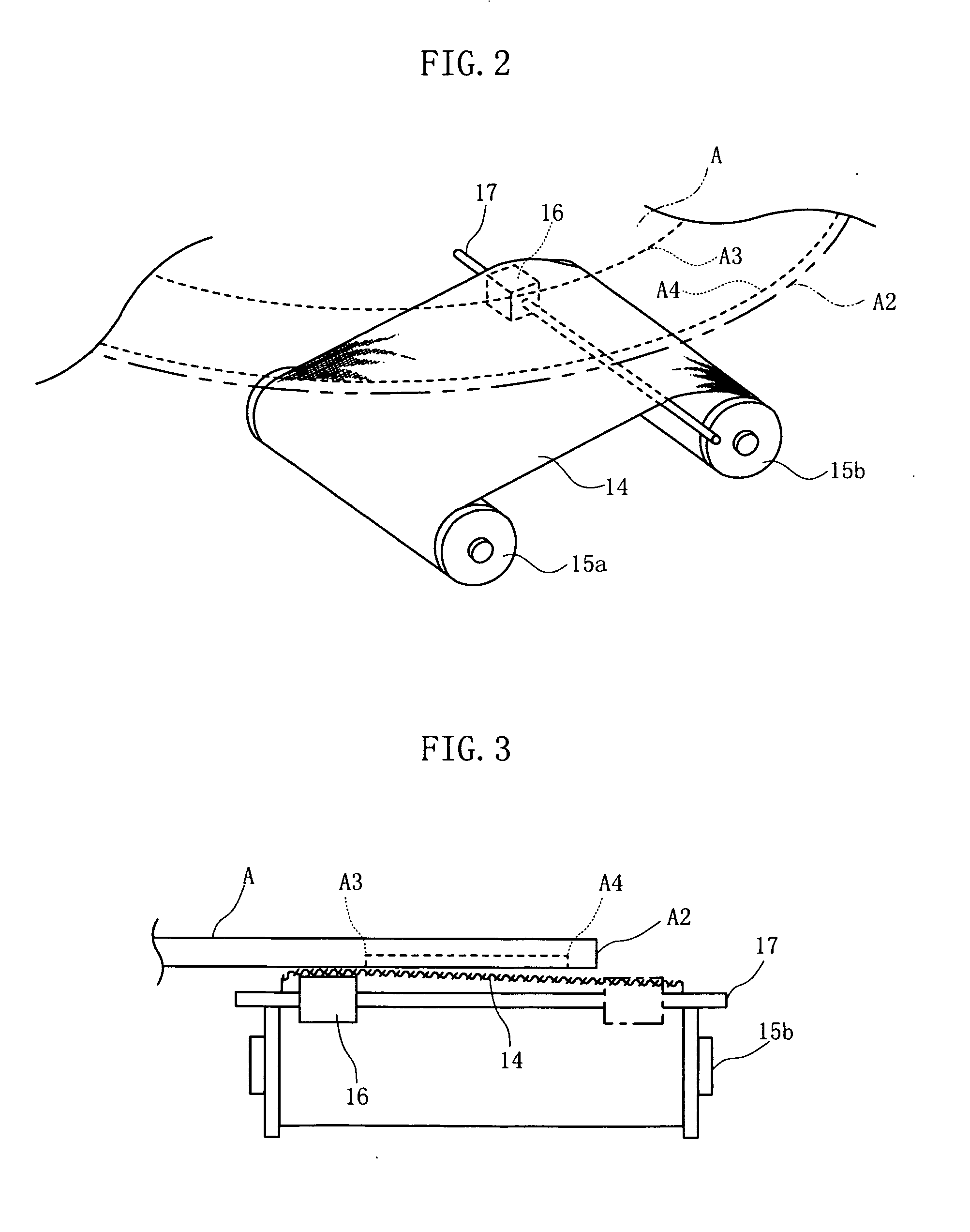
[0037] The disc cleaner relating to the first Embodiment is a cleaner exclusively used for a disc A, such as CD or DVD, and it is equipped with a motor 10, worm gears 11a and 11b, a gear for disc rotation 11c, a belt for disc rotation 11d, a disc spindle 11e, a deceleration gear 11f, a cartridge shell 12, a transmission gear 13a, a movement belt 13b, a cleaning cloth (cleaning member) 14, winding bobbins 15a and 15b, a press member 16 and a guide rod 17, generally. In the disc A, the reading surface is positioned downward over these components, and a hub A1 is set to the cleaner body so as to match-up with the disc spindle 11e. In the disc A, the range from the broken line A3 at the internal circumference side to the broken line A4 at the external circumference side is regarded as a recording region.
[0038] The motor 10, the worm gears 11a and 11b, the gear for disc rotation 11c, the belt for disc rotation 11d, disc spindle 11e and the deceleration gear 11f are established at the pre...
third embodiment
[0064] an efficacy of leaving no wiped trace of dust, and another efficacy of more greatly enhancing the wiping efficacy can be obtained.
[0065] The fourth Embodiment is explained next. For aspects similar to those in the above-described first through third Embodiments, the explanation is omitted.
[0066]FIG. 12 is a top view that shows the fourth Embodiment, FIG. 13 is a side view of the fourth Embodiment, and FIG. 14 is a side view that shows the main section of the fourth Embodiment. The disc cleaner relating to the fourth Embodiment is also a cleaner that is exclusively used for the disc A, and is equipped with a motor for disc rotation 40a, a belt for disc rotation 40b, a disc rotation shaft 40c, a motor for stage movement 41a, pulleys 41b, a pulley belt 41c, a slide stage 42a, a slide guide 42b, a cleaning cartridge 43, a cleaning cloth 44, winding bobbins 45a and 45b, a press member 46 and a motor for winding 47, generally inside the cleaner body.
[0067] The motor for disc rot...
fifth embodiment
[0076] Therefore, it can be utilized as suitable for cleaning the built-in disc B, such as MD or MO, and the efficacies that are similar to those in the above-described Embodiments can be obtained.
[0077] The present invention shall not be limited to each of the Embodiments.
[0078] For example, as a modified example of the first Embodiment, as shown in FIG. 17, a pad 16B with a pointed extremity configuration that is pointed to some extent, which is formed from an elastic body, such as rubber, can be established to the press member 16 as a portion to press the cleaning cloth 14. With this pad 16B, the cleaning cloth 14 is elastically pressed against the reading surface of the disc A in a line contact state, so this makes the convolution of comparatively large and hard dust particles generally difficult, and a scratch on the reading surface by the dust can be efficiently prevented. It is needless to say that this pad 16B shall not be limited to the first Embodiment but can be adopted...
PUM
 Abstract
Description
Claims
Application Information