Concentric tube heat exchanger end seal therefor

a technology of heat exchanger and end seal, which is applied in the direction of heat exchanger sealing arrangement, indirect heat exchanger, light and heating apparatus, etc., can solve the problems of significant increase in weight and cost of heat exchanger, and the difficulty of sealing the annular passageway by tube deformation

Inactive Publication Date: 2005-07-21
DANA CANADA CORP
View PDF58 Cites 19 Cited by
  • Summary
  • Abstract
  • Description
  • Claims
  • Application Information

AI Technical Summary

Problems solved by technology

For example, in aluminum concentric tube heat exchangers, it has proven difficult to seal the annular passageway by deformation of the tubes.
This has led some manufacturers to seal the annular passageway with machined aluminum end blocks, which significantly increase the weight and cost of the heat exchanger.

Method used


Image

  • Concentric tube heat exchanger end seal therefor
  • Concentric tube heat exchanger end seal therefor
  • Concentric tube heat exchanger end seal therefor

Examples


Embodiment Construction

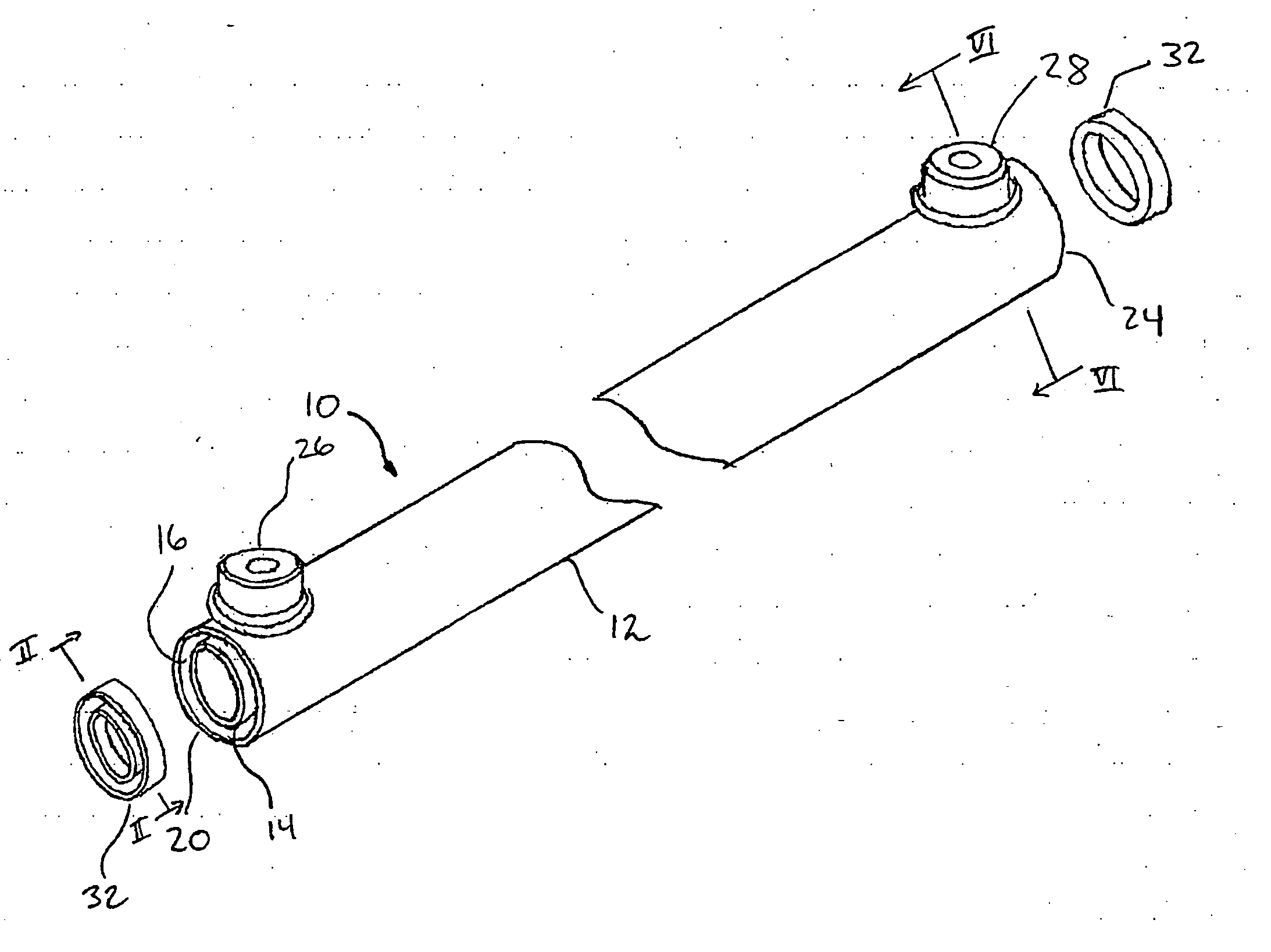
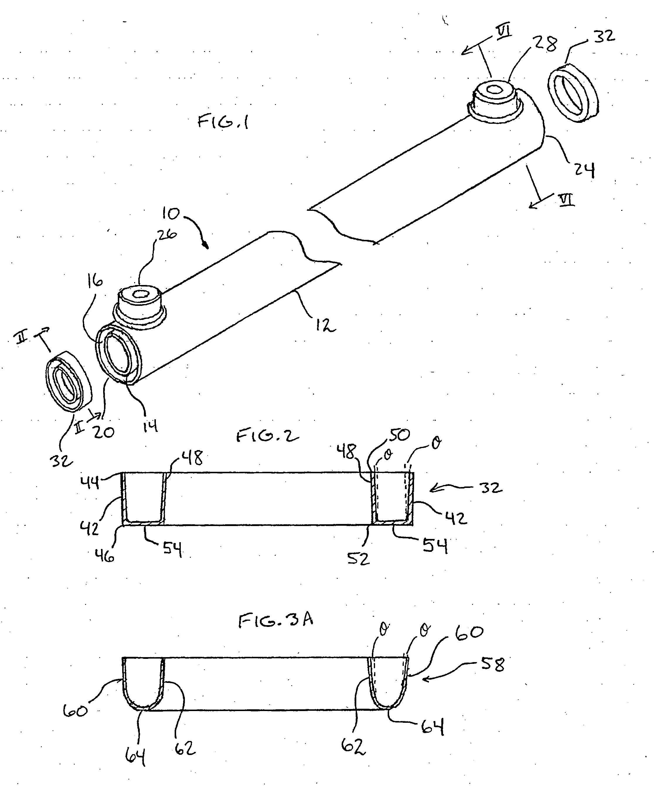
[0018]FIG. 1 illustrates a preferred concentric tube heat exchanger 10 according to the invention. Heat exchanger 10 comprises an outer cylindrical tube 12 and an inner cylindrical tube 14, the inner tube 14 being received in the outer tube 12 and concentric therewith, with an annular passageway 16 being formed between the outer and inner tubes 12, 14 and extending through substantially the entire length of the heat exchanger 10.

[0019] Heat exchanger 10 further comprises an inlet port 18 located adjacent its first end 20 and an outlet port 22 (FIG. 6) located adjacent its second end 24. Both the inlet and outlet ports 18, 22 comprise perforations formed in the outer tube 12 through which a fluid to be cooled, such as oil, is allowed to enter and exit the annular passageway 16. The heat exchanger 10 further comprises an inlet filting 26 and an outlet filting 28 which are mounted to the outer surface of the outer tube 12 in communication with the inlet and outlet ports 18, 22 respect...


PUM


Abstract

A concentric tube heat exchanger comprises an outer tube and a concentric inner tube, with an annular passageway between the tubes. The ends of the annular passageway are sealed by sealing members having axially extending inner and outer walls which are connected to one another and which are sealed to the respective outer and inner tubes. The sealing member walls are preferably connected by an integrally formed connecting wall. The walls of the sealing member are preferably resilient and diverge so as to form a friction fit with the tubes during assembly of the heat exchanger. The heat exchanger further comprises a turbulizer which comprises a plurality of rows of corrugations defining axially extending flow passages. Preferably, the corrugations have a top land width greater than a bottom land width so that the side walls of the corrugation are radially arranged in the annular passageway. Adjacent corrugations in each row are preferably offset relative to one another by an amount of from about 30 percent to about 40 percent.

Description

FIELD OF THE INVENTION [0001] This invention relates to concentric tube heat exchangers, and more particularly to seals for closing an annular passageway between the inner and outer tubes of such heat exchangers. BACKGROUND OF THE INVENTION [0002] Concentric tube heat exchangers are commonly employed as transmission and transaxle oil coolers and are mounted in the coolant tank or manifold of a vehicle radiator. These heat exchangers include a cylindrical outer tube, a cylindrical inner tube and a turbulizer placed in an annular passageway between the inner and outer tubes. Oil is admitted to the annular passageway via an inlet port located at one end of the tube for passage through the turbulizer. The oil is cooled and exits via an outlet port located near the other end of the outer tube. [0003] Numerous arrangements are known in the prior art for sealing the ends of the annular passageway. These include deformation of the inner and / or outer tubes, for example as shown in U.S. Pat. ...

Claims


Application Information

Patent Timeline
Patent Type & Authority Applications(United States)
IPC IPC(8): F28D7/10F28F9/02
CPCF28D7/106F28F2230/00F28F9/0234F28F9/0202
Inventor SEAGER, JAMES R.
Owner DANA CANADA CORP
Why Eureka
Try Eureka