Method and apparatus for wire termination on outwardly spooled multi-pole stators

a multi-pole stators and wire termination technology, which is applied in the direction of winding connections, electrical equipment, manufacturing dynamo-electric machines, etc., can solve the problems of affecting the operation of the winding machine, the end protruding a certain amount beyond the terminal, and the manoeuvre of terminating without blocking the wire is risky,

Inactive Publication Date: 2005-07-21
PONZIO MASSIMO +1
View PDF7 Cites 11 Cited by
  • Summary
  • Abstract
  • Description
  • Claims
  • Application Information

AI Technical Summary

Benefits of technology

[0035] The means for cutting the wire can be associated to a deflector movable parallel to the axis and suitable for folding the portion of cut wire protruding from a terminal bending along an end of same before the start of winding.
[0036] When the terminal is arranged peripherally on the pole means can be provided for pushing the portion of cut wire bent along the terminal side at least during the first winding phases. Preferably, such pushing means comprise an element associated to the shroud that extends from the shroud in a direction orthogonal to the axis, the pushing element being biased by a spring.

Problems solved by technology

Instead, when winding stators with external poles, with a flier, the position of the termination tools interferes with the movement of the flier, and they are therefore complex to arrange.
On the other hand, a manoeuvre of terminating carried out without blocking the wire is risky, even with a terminal with special auto blocking shape, owing to the tension on the wire stretched by the flier, which can cause it to disengage.
A further problem is that, when introducing an end of wire in a terminal, the end protrudes of a certain amount beyond the terminal, and has to be trimmed.
This has the risk that the off-cut portion can sometimes jam into the machine or remain accidentally wound in the stator, causing in both cases a serious drawback.

Method used


Image

  • Method and apparatus for wire termination on outwardly spooled multi-pole stators
  • Method and apparatus for wire termination on outwardly spooled multi-pole stators
  • Method and apparatus for wire termination on outwardly spooled multi-pole stators

Examples


Embodiment Construction

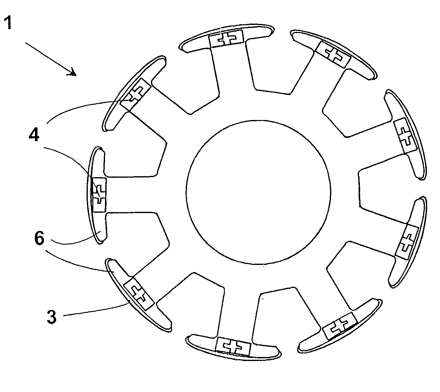
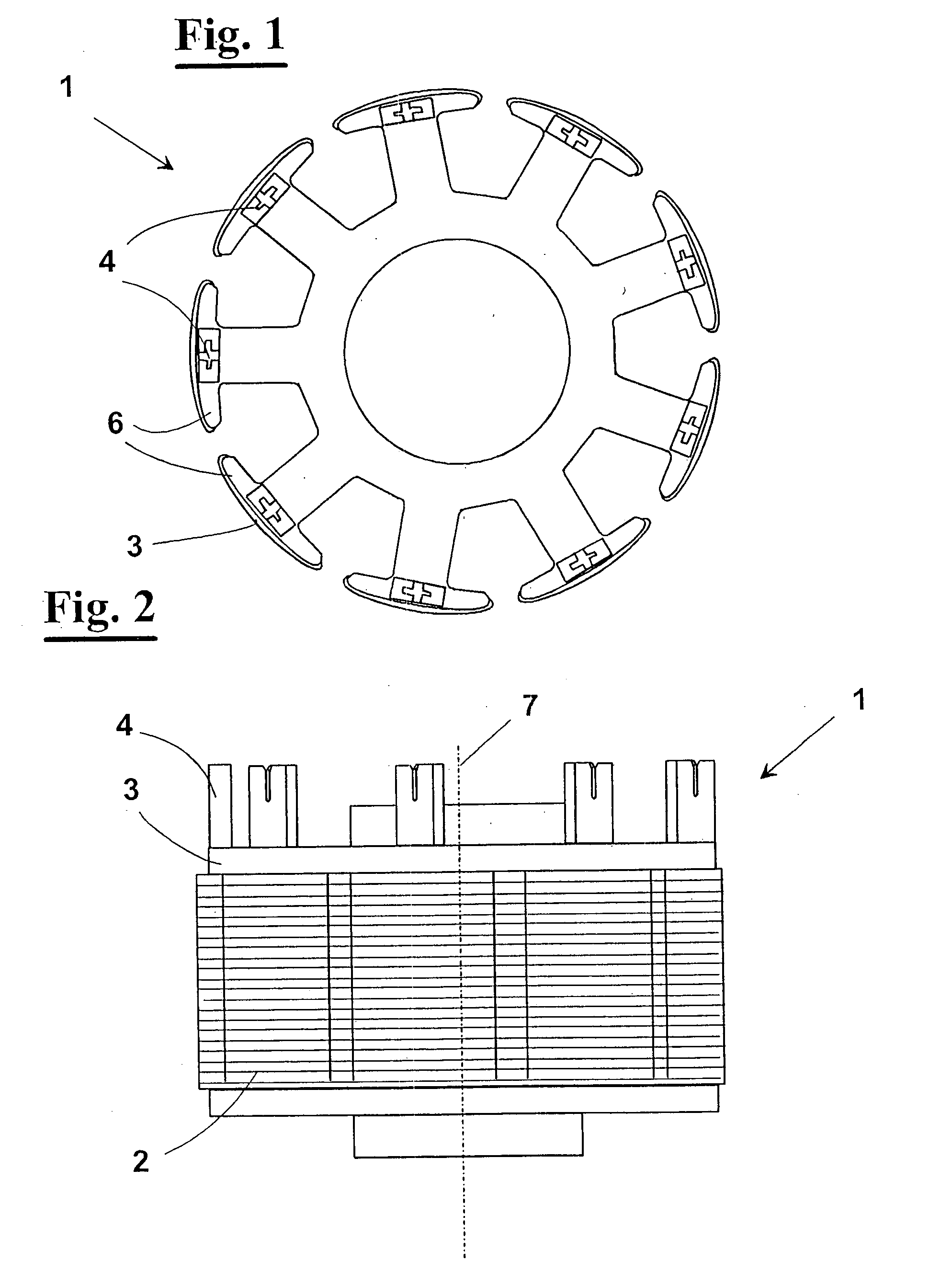
[0052] With reference to FIGS. 1 and 2, an outwardly spooled multi-pole stator 1 has a core formed by a stack of ferromagnetic sheets 2, having an axis of symmetry 7 and a plurality of poles 6 that radially extend defining grooves between them. Stack 2 is in part covered by a terminal board 3 that has a plurality of terminals 4. Terminals have a slit wherein has to be inserted a terminal of wire spooled about poles 6.

[0053] A winding step, for example, is shown in FIG. 14. Wire 15 is wound about poles 6 distributed by a rotatable arm 10, or flier, having a needle end 11. Wire 15 slides through flier 11, while it is kept stretched and fed by means not shown, and known to a person skilled in the art. At winding, wire is guided by shrouds 16 that move radially with respect to stator 1 thus overlapping the respective pole 6. In FIG. 14, a pole 6 already wound with a coil 5 is shown on the right edge of the stator, with an end 5′ that engages a terminal 4.

[0054] Before and after windin...


PUM

PropertyMeasurementUnit
heightaaaaaaaaaa
movementaaaaaaaaaa
ferromagneticaaaaaaaaaa

Abstract

A method and device for wire termination on stators (1) wherein the wire (15) is wound about poles (6) distributed by a flier (10), guided by shrouds (16) that move radially with respect to the stator (1) overlapping the respective pole (6). Wire termination operations are provided on the wire ends (15) into the terminals (4) with the aid of the flier (10), carried out by an apparatus equipped with a termination device (20), comprising a first deflector (21), a second deflector (22), a blade (23), and a clamp formed by a movable gripper (24) and a fixed gripper (25). The movable gripper is suitable for closing onto the fixed gripper for gripping the wire (15). The device (20) can carry out the steps of catching, moving, introducing and cutting the wire (15) with movements parallel to its own axis (27), or to the axis (7) of the stator (1).

Description

CROSS REFERENCE TO RELATED APPLICATIONS [0001] This application is a continuation of U.S. application Ser. No. 10 / 406,471, filed on Apr. 3, 2003, which application claims foreign priority under 35 U.S.C. §119 to European Patent Application No. 02425221.5, which application was filed on Apr. 10, 2002.FIELD OF THE INVENTION [0002] The present invention relates to the field of stator winding machines, and precisely it relates to a method for wire termination on outwardly spooled multi-pole stators. Furthermore, the invention relates to an apparatus that carries out this method. BACKGROUND OF THE INVENTION [0003] Outwardly spooled multi-pole stators are known, formed by a substantially star-shaped stack of sheets featuring a plurality of poles extending from a tubular core. The stators of this type are suitable for coupling with an inner concentric armature or outer ring armature. They are common in brushless motors. [0004] The peripheries of the poles, or pole extensions, form substant...

Claims


Application Information

Patent Timeline
Patent Type & Authority Applications(United States)
IPC IPC(8): H02K15/00H02K15/085
CPCH02K15/0056H02K15/0075Y10T29/5141Y10T29/49009Y10T29/49073Y10T29/53143Y10T29/49071H02K15/0068
Inventor PONZIO, MASSIMOGIACHETTI, ROBERTO
Owner PONZIO MASSIMO
Why Eureka
Try Eureka