Optical modulator of electron beam

a technology of optical modulator and electron beam, which is applied in the manufacture of electrode systems, electric discharge tubes/lamps, instruments, etc., can solve the problems of limited application range, low current density, and difficulty in achieving high frequency modulation of beams using this approach

Inactive Publication Date: 2005-07-21
APPLIED NANOTECH HLDG
View PDF13 Cites 3 Cited by
  • Summary
  • Abstract
  • Description
  • Claims
  • Application Information

AI Technical Summary

Problems solved by technology

However, this method produces low electron currents (emittance), much lower than that of thermionic cathodes, which limits a range of possible applications.
Electrons are generated by the photocathode, and the electron current is limited by the performance and properties of the photocathode, resulting in current density that is usually low.
However, it is difficult to achieve high frequency modulation of the beam using this approach.
The problem with using cold cathodes in this application is the cathode-to-grid capacitance, which leads to a low input impedance at higher frequencies.

Method used


Image

  • Optical modulator of electron beam
  • Optical modulator of electron beam

Examples


Embodiment Construction

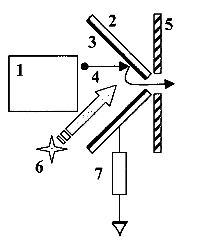
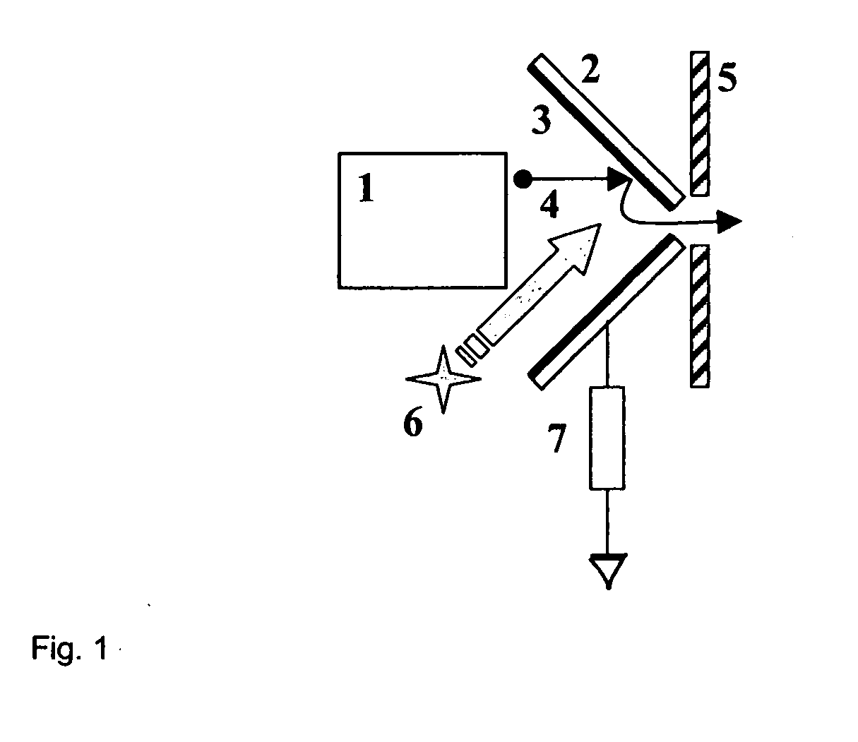
[0007] Described is an electron source with an optically active electron concentration cavity, meaning that the cavity has a coating made of a semiconducting material that changes its electrical properties when irradiated by a light source. The property that changes under the influence of the light source is the conductivity of the coating. For example, if the coating is not irradiated by light, it has high electrical conductivity, and if it is irradiated by light it has low conductivity. Depending on the conductivity of the cavity, the electron transport to the cavity exit aperture changes. If the cavity is not irradiated by the light, the electrons will be transported to the aperture under the influence of an external electric field induced in such a way that electrons travel in the direction to the exit aperture. If the cavity is irradiated by a light source, the electrons will transport through the optically active coating to the conducting or semiconducting body of the cavity. ...


PUM


Abstract

An optoelectronic modulator is based on the concentration of an electron beam from an electron gun by a tapered cavity, which sides are photosensitive and change the electrical conductivity under the illumination of light (electromagnetic radiation). The light modulation causes the corresponding changes in the current transported across the walls of the cavity. The remaining part of the electron current exits the cavity aperture and forms an amplitude-modulated divergent electron beam.

Description

CROSS-REFERENCE TO RELATED APPLICATIONS [0001] The present application claims priority to U.S. Provisional Patent Application Ser. No. 60 / 536,856.TECHNICAL FIELD [0002] The present invention relates in general to modulation of an electron beam BACKGROUND INFORMATION [0003] Numerous applications require high brightness, high frequency electron sources. Those include military, aerospace, communications and other commercial industries. Advances in modern technology require higher performance of electron sources that can be used for generation of powerful microwave radiation. One of the ways to achieve a high-brightness electron beam with desired parameters is to use a photocathode irradiation technique. However, this method produces low electron currents (emittance), much lower than that of thermionic cathodes, which limits a range of possible applications. [0004] U.S. Pat. No. 4,313,072 describes an electron gun in which the electron beam is modulated by laser pulses illuminating a ph...

Claims


Application Information

Patent Timeline
Patent Type & Authority Applications(United States)
IPC IPC(8): H01J3/08H01J21/04H01J29/52
CPCH01J3/08H01J29/52H01J21/04
Inventor YANIV, ZVIPAVLOVSKY, IGORFINK, RICHARD LEE
Owner APPLIED NANOTECH HLDG
Why Eureka
Try Eureka