Process control loop current verification

a technology of control loop and loop current, applied in the field of process devices, can solve the problems of limiting the accuracy of the transmitted process variable, the accuracy at which the loop current can be set, and the control loop current may be susceptible to drifting

Inactive Publication Date: 2005-08-04
ROSEMOUNT INC
View PDF20 Cites 57 Cited by
  • Summary
  • Abstract
  • Description
  • Claims
  • Application Information

AI Technical Summary

Problems solved by technology

When an analog loop current is used to represent information such as a process variable, the accuracy at which the loop current can be set can be a limiting factor on the accuracy of the transmitted process variable.
The controlled loop current may be susceptible to drifting.

Method used


Image

  • Process control loop current verification
  • Process control loop current verification
  • Process control loop current verification

Examples


Embodiment Construction

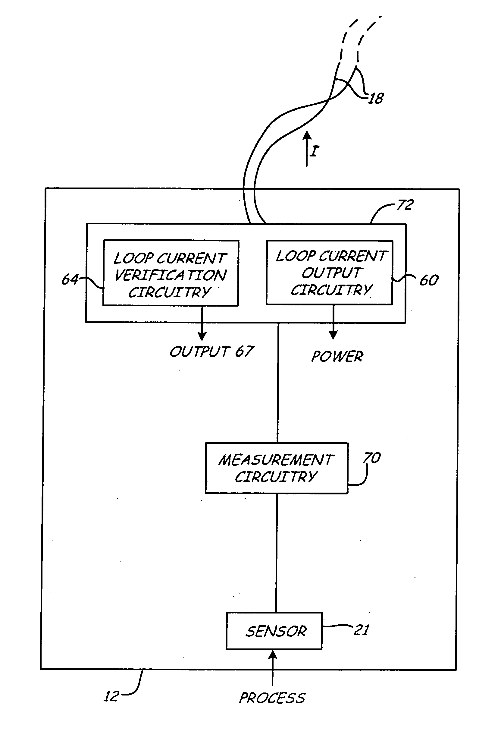
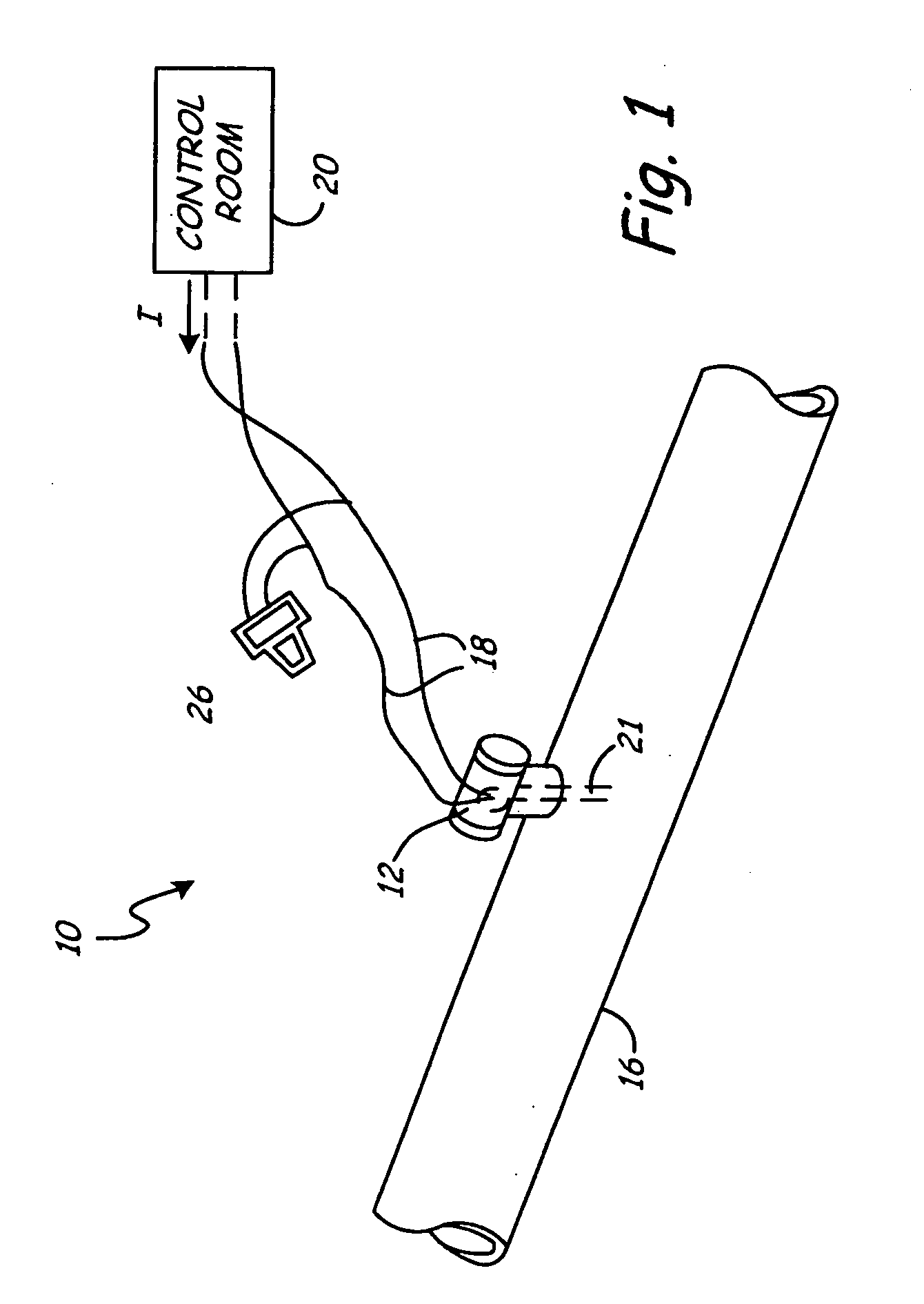
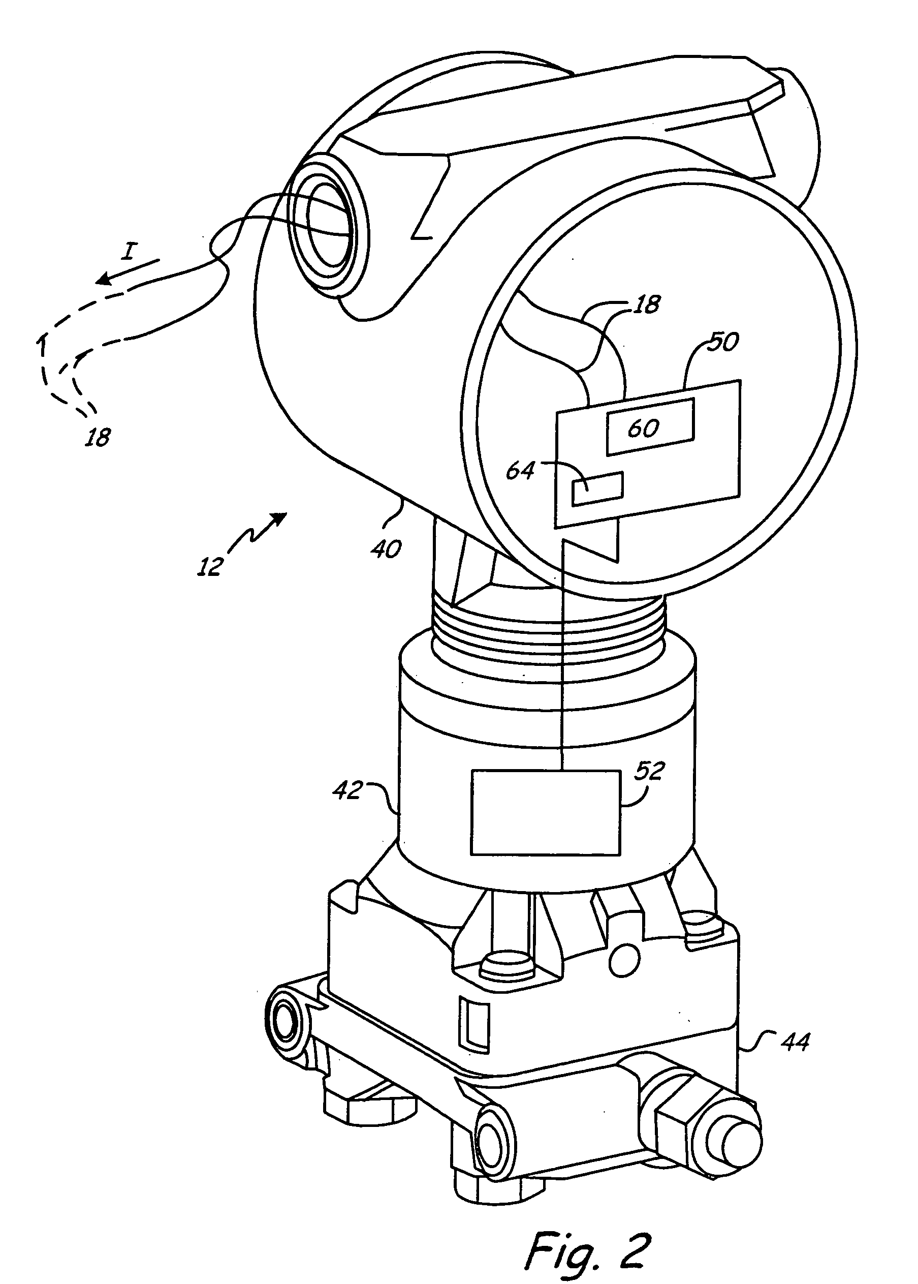
[0021] The present invention provides an analog loop current verification technique for verifying that the current applied to a process control loop by a process device is set to a desired value. Loop current verification circuitry is used to detect errors in an applied current output level. At least a portion of the loop current verification circuitry is independent from circuitry used to set the loop current on the process control loop. This provides independent (or redundant) verification of the process control loop current. The invention can be implemented in any process device which is used to control current in a process control loop and is not limited to the illustrative process device discussed herein. For example, one process device described herein is a transmitter which includes a sensor for sensing a process variable. The transmitter controls the current flowing through the process control loop to an analog value which is representative of the sensed process variable. Ho...


PUM


Abstract

A process device is configured for coupling to a two wire process control loop. Loop current output circuitry is configured to apply an output current to the two wire process control loop. Loop current verification circuitry is coupled to the two wire process control loop and configured to detect errors in the applied output current. At least a portion of the loop current verification circuitry is independent from the loop current output circuitry.

Description

[0001] The present application is a Continuation-In-Part of and claims priority of U.S. patent application Ser. No. 10 / 733,558, filed Dec. 11, 2003, which is a Continuation-In-Part U.S. patent application Ser. No. 10 / 635,944, filed Aug. 7, 2003, the contents of which are hereby incorporated by reference in their entirety.BACKGROUND OF THE INVENTION [0002] The present invention relates to process devices of the type used in industrial processes. More particularly, the present invention relates to devices such as transmitters which control electrical current in a process control loop. [0003] Field devices such as process controllers, monitors and transmitters, are used in the process control industry to remotely control, monitor or sense a process variable. For example, a process variable may be transmitted to a control room by a transmitter for use in controlling the process or for providing information about process operation to a controller. For example, information related to pres...

Claims


Application Information

Patent Timeline
Patent Type & Authority Applications(United States)
IPC IPC(8): G01R19/25G08C19/02
CPCG01R19/2509G05B19/0425G08C19/02G05B2219/25428G05B2219/25189
Inventor LONGSDORF, RANDY J.HUISENGA, GARRIE D.JOHNSON, JAMES A.
Owner ROSEMOUNT INC
Why Eureka
Try Eureka