Hand operated shirring machine

a shirring machine and hand-operated technology, which is applied in the field of hand-operated shirring machines, can solve the problems of increasing the capital cost of equipment, the time required for changing the stuffing tube, and the reduced packaging efficiency of the machine,

Inactive Publication Date: 2005-08-18
MEATECH
View PDF12 Cites 3 Cited by
  • Summary
  • Abstract
  • Description
  • Claims
  • Application Information

AI Technical Summary

Benefits of technology

[0009] If the casing comprises an open net, then a plurality of spring-loaded fingers may extend from the end of the tubular body. The fingers may be connected to a continuous circumferential spring which draws the fingers inwardly. Forward movement of the fingers causes them to engage and push the netting forward over the stuffing tube. Rearward movement causes the fingers to move outwardly against the spring force so that the fingers run over the surface of the casing without it being drawn from the stuffing tube. Movement in the opposite direction causes the fingers to engage the casing and again force it onto the stuffing tube.

Problems solved by technology

This is obviously a time consuming process and reduces the packaging efficiency of the machine.
However, one disadvantage is the increased capital cost of the equipment and also the time required to change over the stuffing tube.
In addition, in some processes or with some machines, it is not possible to change the stuffing tube.

Method used


Image

  • Hand operated shirring machine
  • Hand operated shirring machine
  • Hand operated shirring machine

Examples


Embodiment Construction

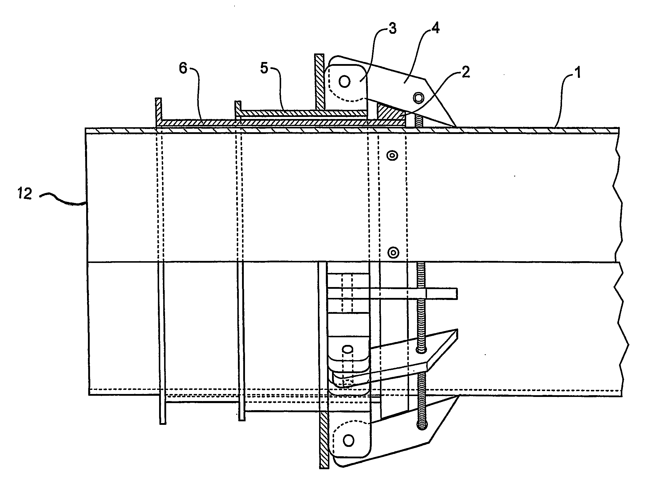
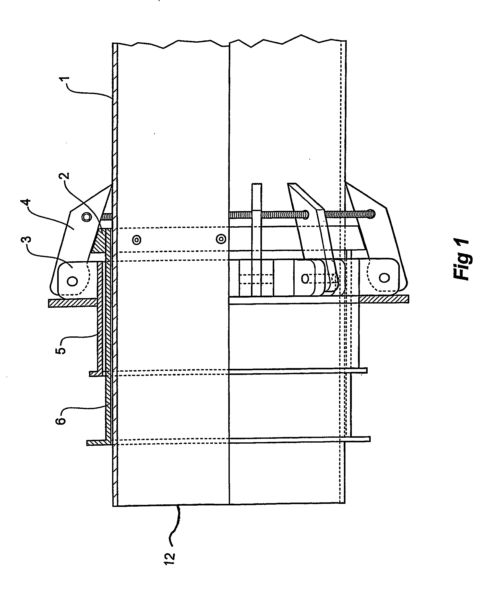
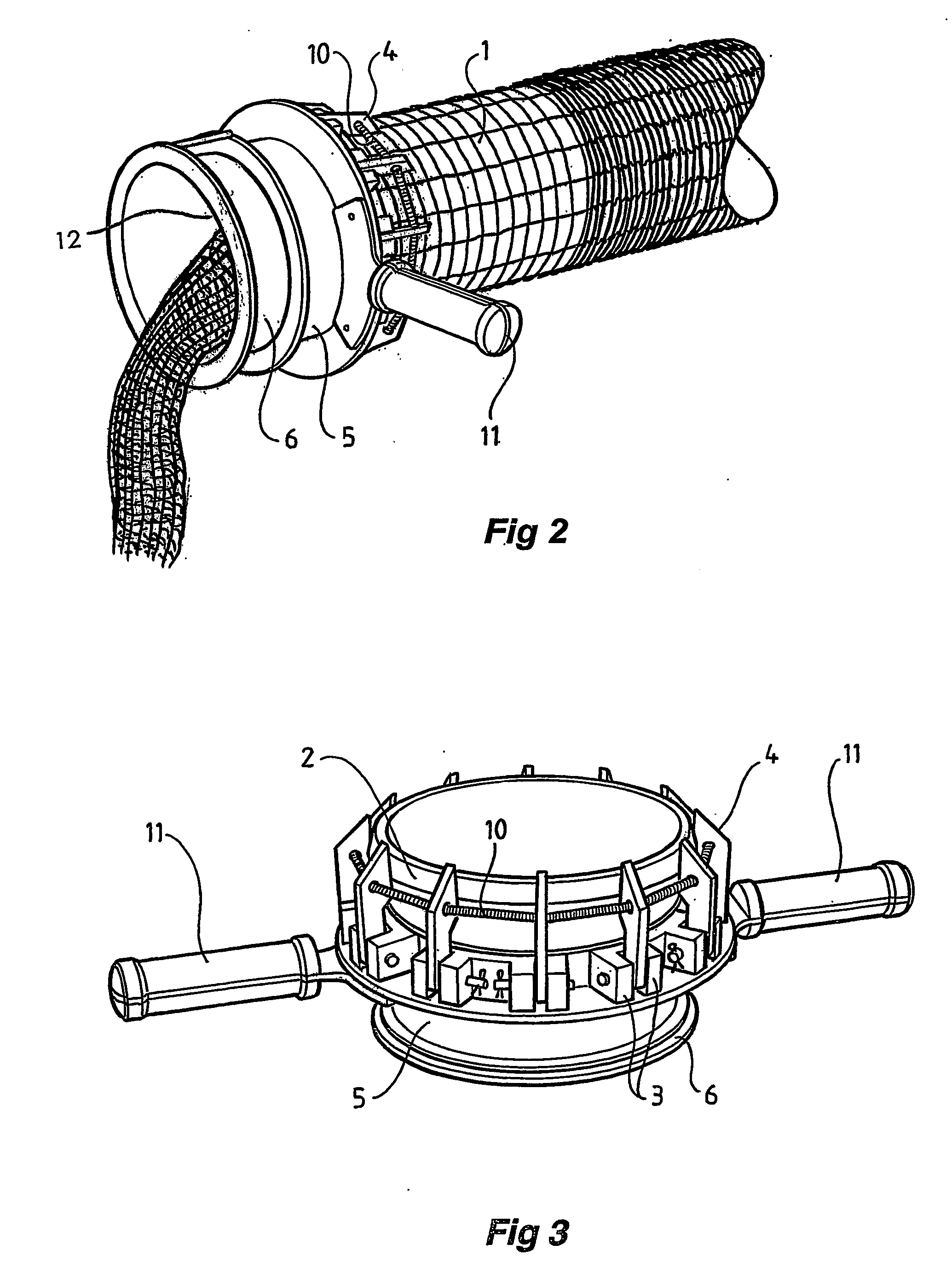
[0015] Referring to FIG. 1, the shirring machine is shown located over a stuffing tube 1 having a discharge end 12. The tubular body comprises a first tube 5 that locates over the outer surface of the second tube 6. The second tube 6 locates over the stuffing tube 1. A plurality of mounting brackets 3 are attached to and spaced around the outer surface of the first tube 5. Fingers 4 are pivotally attached to the mounting brackets 3 and extend forward of the first tube 5.

[0016] A circumferential coil spring 10 locates through each of the fingers 4 forward of the pivot point of the fingers 4. The coil spring 10 has the effect of drawing the fingers 4 inwardly towards the stuffing tube 1. The first tube 5 slides with respect to the second tube 6. Disengaging means comprising a ring 2 having a tapered exterior section upon which fingers 4 rest is located on the forward end of the second tube 6 and forces the fingers 4 apart as the first tube 5 slides rearwardly with respect to the seco...


PUM


Abstract

A hand-operated machine for shirring casing onto a stuffing tube (1) includes a body through which the stuffing tube (1) covered in casing may pass. The shirring machine has casing engaging means (4) that engages the casing as the machine is pushed along the stuffing tube (1) from the discharge end (12) so that the casing is drawn onto the stuffing tube. The casing engaging means (4) also disengages the casing when it is pulled in the opposite direction. The shirring machine also includes grasping means (11) to manually move it back and forth along the stuffing tube (1).

Description

FIELD OF THE INVENTION [0001] This invention relates to a hand operated shirring machine and in particular to a hand operated machine used to load casing material on the stuffing tube of a food packaging machine. BACKGROUND OF THE INVENTION [0002] Food packaging machines that are used to produce continuous or discontinuous food products such as salamis or whole muscle product encased in netting force the food product through a stuffing tube so that it is extruded or forced into packaging that is drawn off the stuffing tube. In the case of salami, moistened casing material is fed onto the outer surface of the stuffing tube. This is known as shirring the casing onto the stuffing tube. The end of the casing is clipped and then the food product is forced through the stuffing tube so that the case is pulled from the stuffing tube as it is filled by the food product. [0003] It is similar in the case of whole muscled product which is encased in elastic netting. The elastic netting is shirr...

Claims


Application Information

Patent Timeline
Patent Type & Authority Applications(United States)
IPC IPC(8): A22C13/02
CPCA22C13/02
Inventor MERCURI, ENNIO
Owner MEATECH
Why Eureka
Try Eureka