
Recording tape cartridge

a technology of recording tape and cartridge, which is applied in the field of recording tape cartridge, can solve the problems of drive device malfunction, recording/reproducing operation cannot be performed, and recording tape cartridge damag

Active Publication Date: 2005-08-25
FUJIFILM HLDG CORP +1
View PDF27 Cites 19 Cited by
  • Summary
  • Abstract
  • Description
  • Claims
  • Application Information

AI Technical Summary

Benefits of technology

[0012] Accordingly, it is an object of the present invention to provide a recording tape cartridge which is constructed such that when in non-use, a reel can not be released from being the rotation-locked state by a brake member.

Problems solved by technology

If the recording tape cartridge is loaded into a drive device under such a condition, there tends to arise a problem that not only the recording / reproducing operation cannot be performed but also the recording tape cartridge is damaged or the drive device malfunctions.
Another problem is that since the reel becomes rotatable when in non-use, the recording tape tend to get wrinkled or torn off.

Method used


Image

  • Recording tape cartridge
  • Recording tape cartridge
  • Recording tape cartridge

Examples


Embodiment Construction

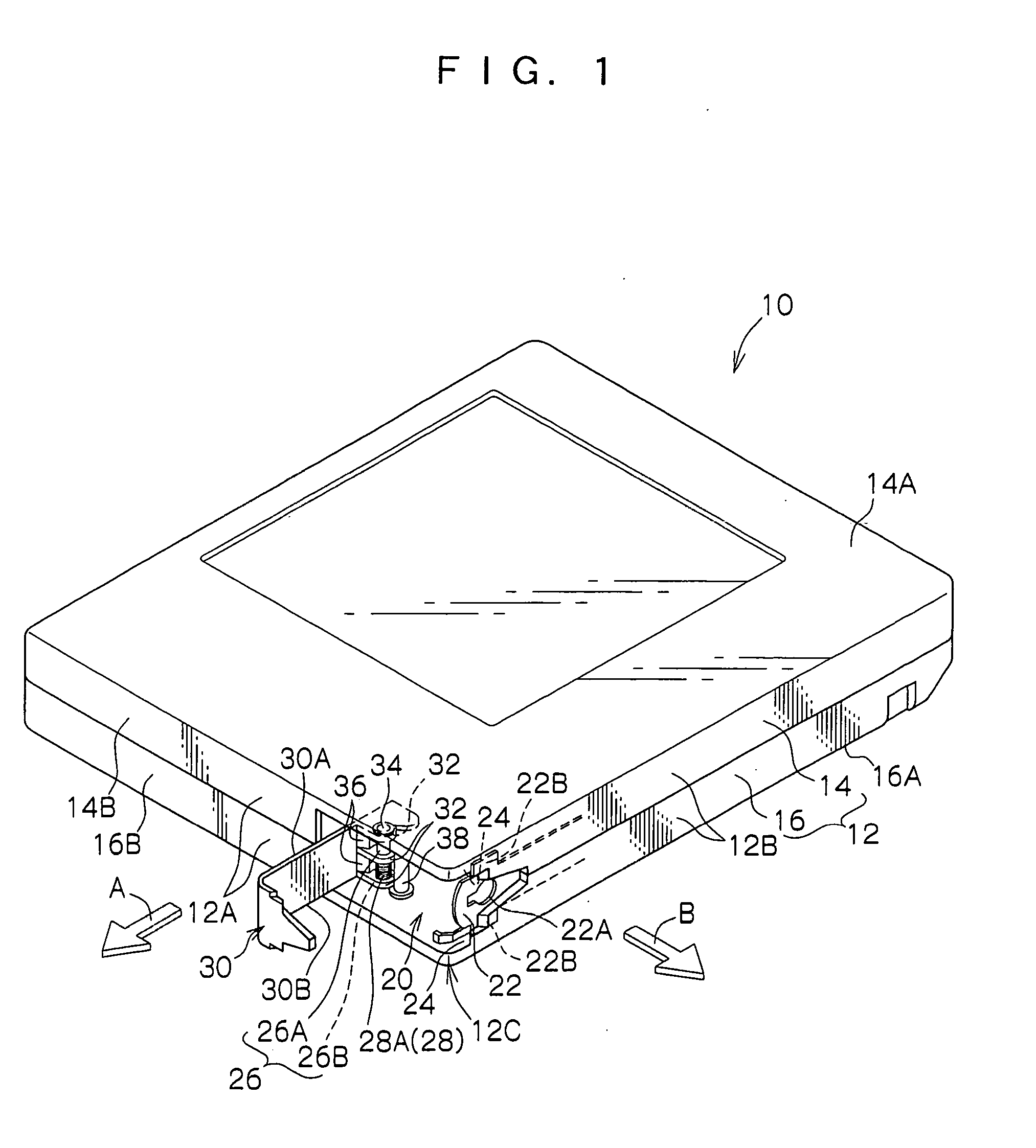
[0034] Embodiments of the present invention will now be described with reference to the drawings. For convenience of description, it is assumed that a front direction. This direction is a direction in which the recording tape cartridge is loaded into a drive device is indicated by an arrow A and is regarded as a front direction, and a left direction is indicated by an arrow B, and with these directions as reference, front and rear, left and right, and up and down directions are defined.

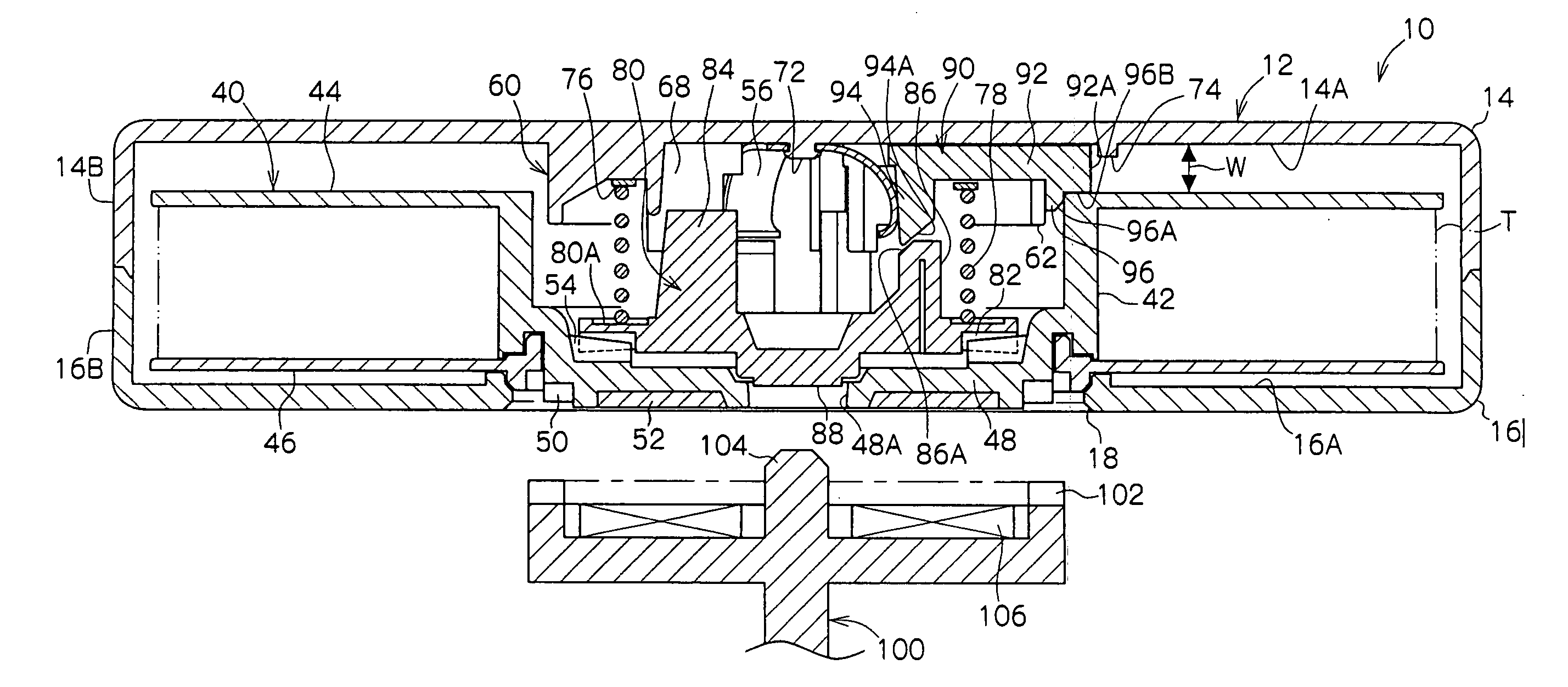
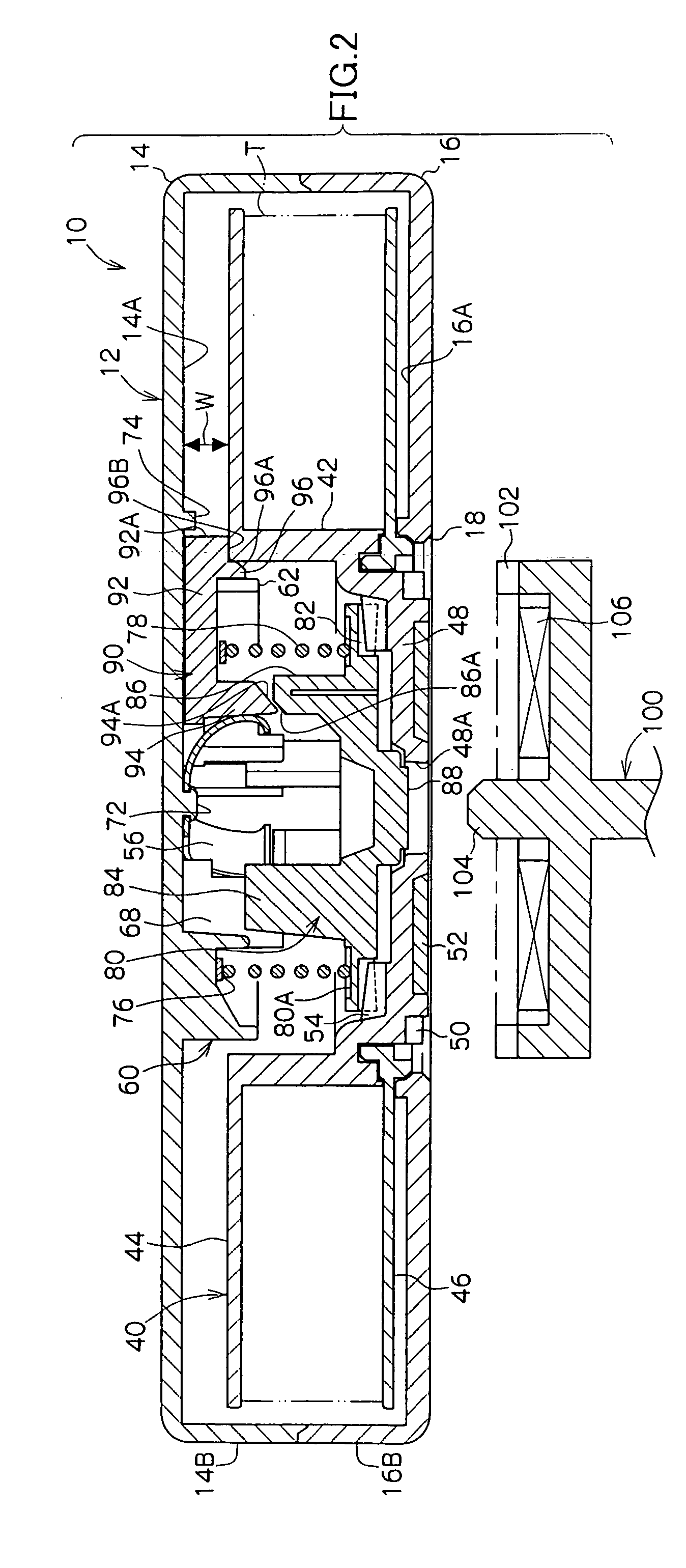
[0035] Referring to FIG. 1, a recording tape cartridge 10 includes a substantially box-shaped case 12 comprising an upper case half 14 and a lower case half 16 each formed from a plastic material such as POLYCARBONATE. The upper and lower case halves 14 and 16 are jointed together by means of screwing or ultrasonic welding, with a peripheral wall 14B projectingly provided at a peripheral edge of a top plate 14A being disposed in abutment with a peripheral wall 16B projectingly provided at a periphera...


PUM


Abstract

A recording tape cartridge includes: a case accommodating a reel on which a recording tape is wound; a brake member provided non-rotatably with respect to the case; a lock member provided in a mounting portion on the inner surface of a top plate of the case to be slidable in a radial direction of the reel; and a falling-out preventing member for keeping the lock member from being removed from the mounting portion. The brake member is arranged to selectively assume a rotation locking position where the brake member is engaged with the reel to prevent the reel from being rotated and a rotation permitting position where the brake member is disengaged from the reel to permit the reel to be rotated. The lock member is arranged, when the brake member assumes the rotation locking position, to be interposed between the upper surface of the reel and a top plate of the case, thereby preventing the reel from being moved axially thereof. The lock member is also arranged, when the brake member is moved from the rotation locking position to the rotation permitting position, to be removed from between the upper surface of the reel and the top plate of the case in response to the movement of the brake member, thereby permitting the reel to be moved axially thereof. When the brake member assumes the rotation locking position, a clearance is defined between the lock member and the brake member, and the clearance is made smaller than the movement stroke of the brake member from the rotation locking position to the rotation permitting position.

Description

CROSS-REFERENCE TO RELATED APPLICATION [0001] This application claims priority under 35 USC 119 from Japanese Patent Application No. 2004-48567, the disclosure of which is incorporated by reference herein. BACKGROUND OF THE INVENTION [0002] 1. Field of the Invention [0003] The present invention relates to a recording tape cartridge. More particularly, the present invention pertains to a recording tape cartridge in which a single reel on which is wound a recording tape such as a magnetic tape usable as a recording and reproducing medium for a computer or the like is accommodated in a case. [0004] 2. Description of the Related Art [0005] There has heretofore been known a recording tape cartridge in which a recording tape such as a magnetic tape usable as a recording and reproducing medium for a computer or the like is wound on a reel, and the reel is rotatably accommodated in a case formed from a plastic material. The recording tape cartridge is arranged such that when in use (when lo...

Claims


Application Information

Patent Timeline
IPC IPC(8): G11B23/04G11B23/087G11B23/107
CPCG11B23/043G11B23/107G11B23/08721
Inventor HIRAGUCHI, KAZUO
Owner FUJIFILM HLDG CORP
Learn More