Sealing material

a sealing material and u-shaped technology, applied in the direction of brake systems, transportation and packaging, machines/engines, etc., can solve the problem of reducing the sealing ability

Active Publication Date: 2005-08-25
MITSUBISHI CABLE IND LTD
View PDF8 Cites 19 Cited by
  • Summary
  • Abstract
  • Description
  • Claims
  • Application Information

AI Technical Summary

Problems solved by technology

However, when the conventional sealing material is applied to medical appliances and paint appliances, liquids used in these appliances mostly tend to solidify (painting materials such as paint) or include components easily crysta...

Method used


Image

  • Sealing material
  • Sealing material
  • Sealing material

Examples


Embodiment Construction

[0018] Preferred embodiments of the present invention will now be described with reference to the accompanying drawings.

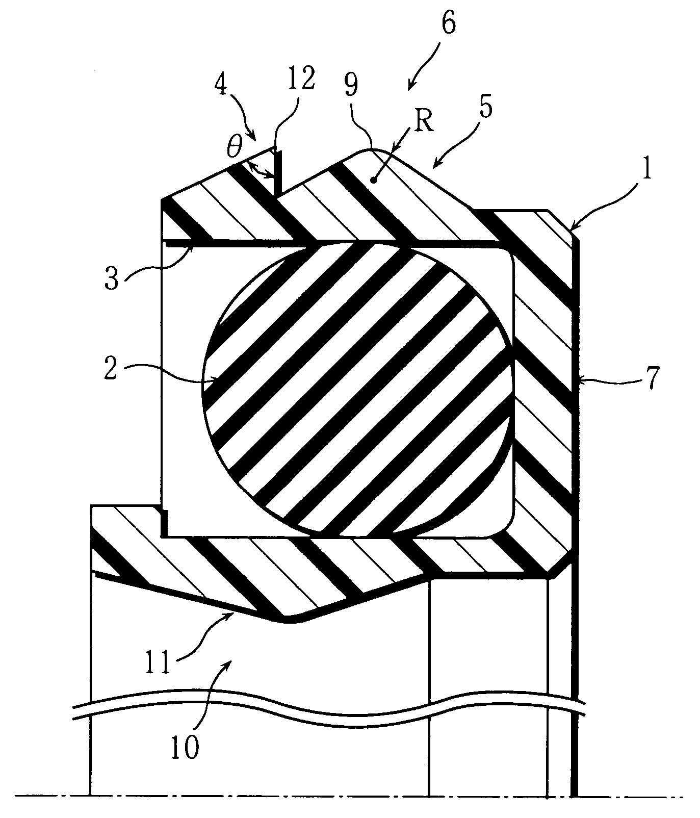
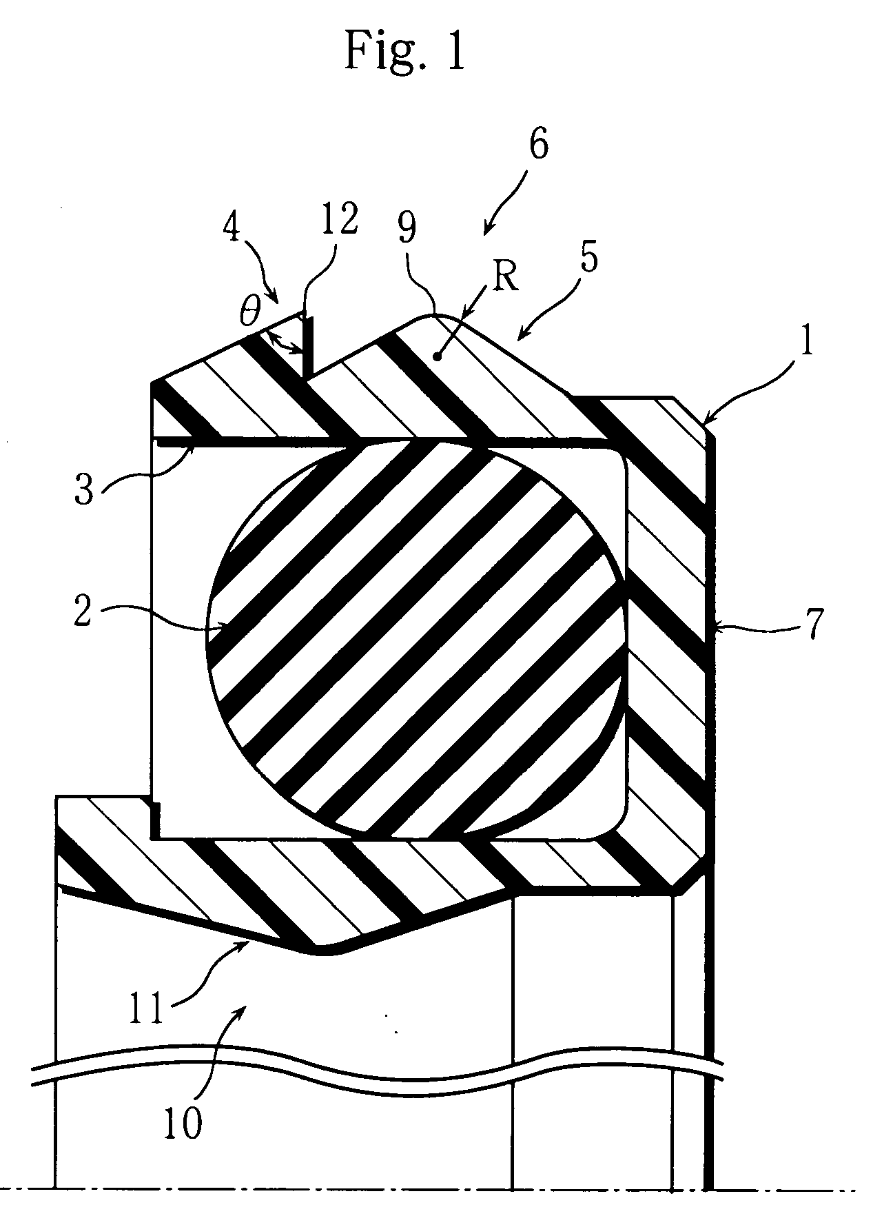
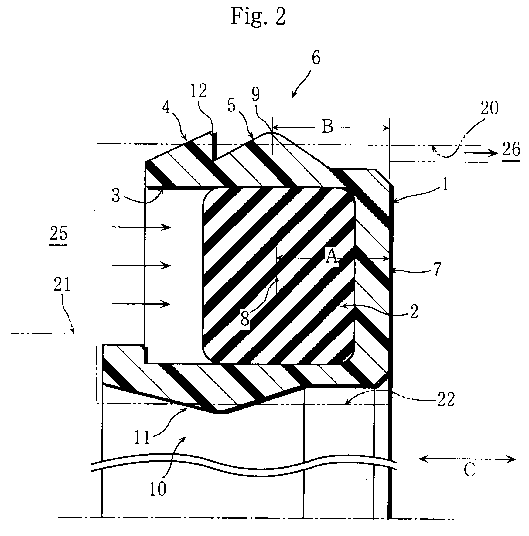
[0019]FIG. 1 through FIG. 4 show first and second embodiments of the present invention. FIGS. 1 and 2 show the first embodiment in which an attachment groove 22 of ring is formed on a peripheral face of a piston 21 reciprocating in a cylinder tube 20 and the material (seal) is attached to the attachment groove 22, and FIGS. 3 and 4 show the second embodiment in which an attachment groove 22 of ring is formed on an inner peripheral face of the cylinder tube 20 (on the head) and the seal is attached to the attachment groove 22. The piston 21 and a piston rod 24 reciprocate in the directions shown by arrows C, and liquid, which tends to solidify or crystallize, is sealed in a fluid-storing space 25 in the cylinder tube 20 (not shown in Figures).

[0020]FIG. 1 and FIG. 3 show a free state, namely, a state before the sealing material (seal) of the present invention, app...


PUM


Abstract

A sealing material for sealing liquid composed of a seal main body of resin, having a U-shaped cross section and a concave groove opening to an axis direction, and an 0-ring of rubber fit to the concave groove of the seal main body used for medical appliances and paint appliances. The seal main body is provided with an end lip portion on a side along the axis direction and a main lip portion on a middle position of the axis direction on a sliding face side, and, in a pressure-receiving state in which pressure works on the side along the axis direction and the O-ring is compressed, a dimension of the axis direction from a base end face of the seal main body on other side along the axis to a cross-section central point of the O-ring and another dimension of the axis direction from the base end face to an end portion of the main lip portion are set to be approximately equal.

Description

BACKGROUND OF THE INVENTION [0001] 1. Field of the Invention [0002] This invention relates to a U-shaped sealing material (sealing member) for reciprocating or rotational movement. [0003] 2. Description of the Related Art [0004] As a conventional sliding (moving) sealing material (sealing member) used for oil-hydraulic or pneumatic appliances, a material (seal) as described below is known. That is to say, the sealing material is composed of a resin ring having U-shaped cross section and a concave groove, and a metal spring fit to the concave groove (refer to Japanese provisional publication No. 8-82372, and No. 2003-247646, for example) or a elastic body of rubber (refer to Japanese provisional publication of utility model No. 5-47624), and, a stage of lip is formed on a sliding face of the resin ring. [0005] However, when the conventional sealing material is applied to medical appliances and paint appliances, liquids used in these appliances mostly tend to solidify (painting materi...

Claims


Application Information

Patent Timeline
IPC IPC(8): F16J15/18F16J15/3236F16J15/3284
CPCF16J15/3236F16J15/3208
Inventor AOSHIBA, HIROSHIKANOU, YASUJI
Owner MITSUBISHI CABLE IND LTD
Why Eureka
Try Eureka