Detachabaly connected tensioning apparatus

a tensioning apparatus and detached connection technology, applied in the direction of instruments, percussion musical instruments, instruments, etc., can solve the problem of wasting a considerable amount of time in removing the tension rods

Inactive Publication Date: 2005-09-01
WHITTINGTON JOEL THOMAS
View PDF4 Cites 6 Cited by
  • Summary
  • Abstract
  • Description
  • Claims
  • Application Information

AI Technical Summary

Problems solved by technology

Removing the tension rods takes a considerable amount of time.

Method used


Image

  • Detachabaly connected tensioning apparatus
  • Detachabaly connected tensioning apparatus
  • Detachabaly connected tensioning apparatus

Examples


Embodiment Construction

—PREFERRED EMBODIMENT—FIGS. 1-3

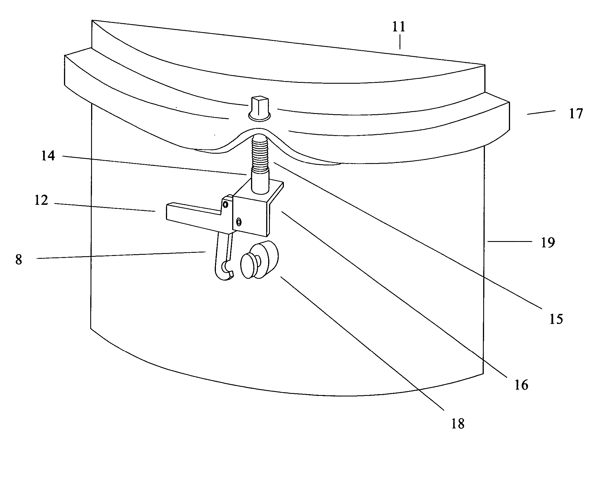
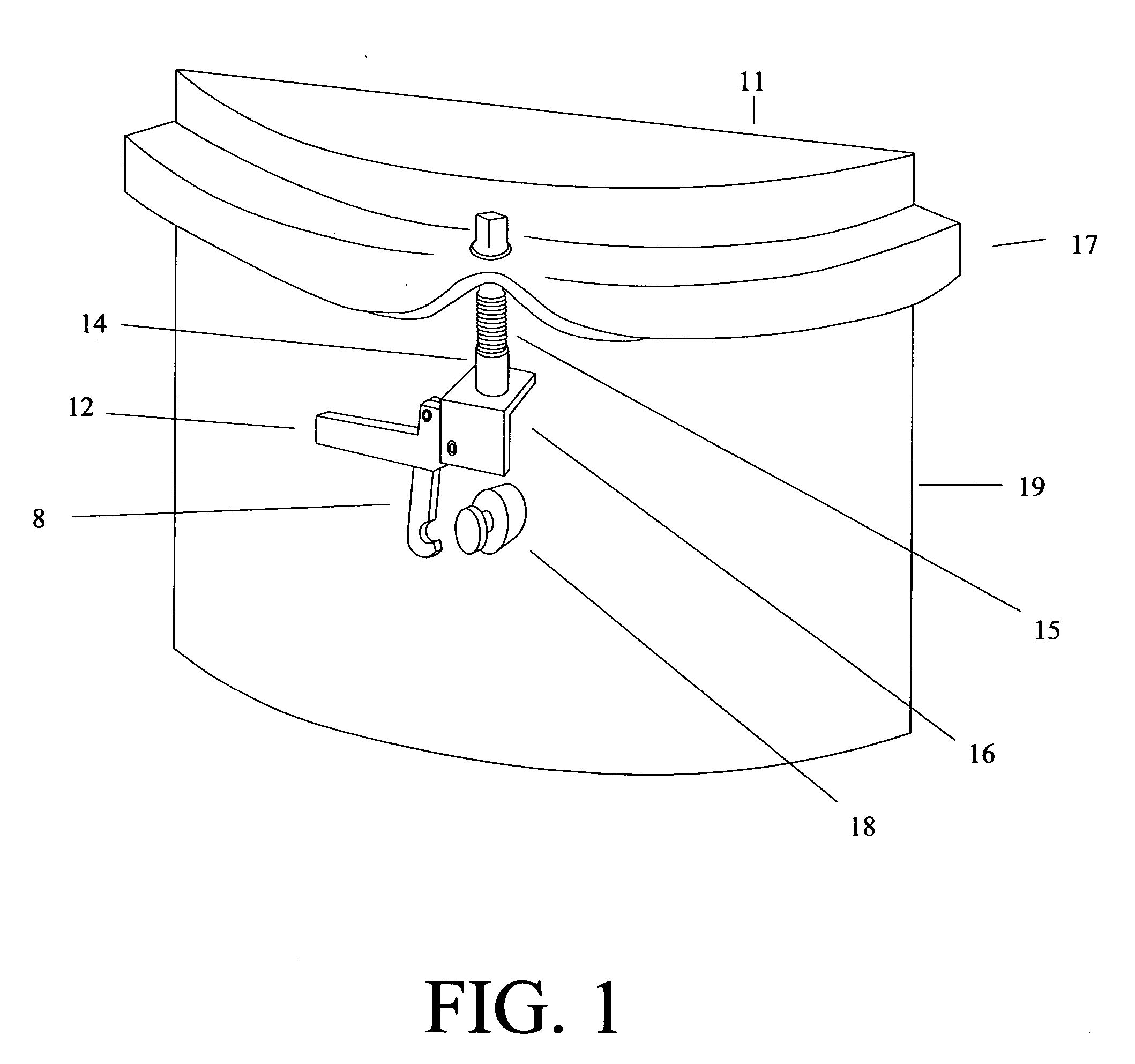
[0015]FIG. 1 provides an isometric view of a detachably connected tensioning apparatus in disconnecting operation from anchor post 18 while being connected to a drum rim 17. The tension rod 15 is connected to a main body 16 of the tensioning apparatus by a lug nut 14. A release arm 12 is in release position to allow a connecting arm 8 to disconnect from an anchor post18. The anchor post 18 is rigidly connected to a drum shell 19.

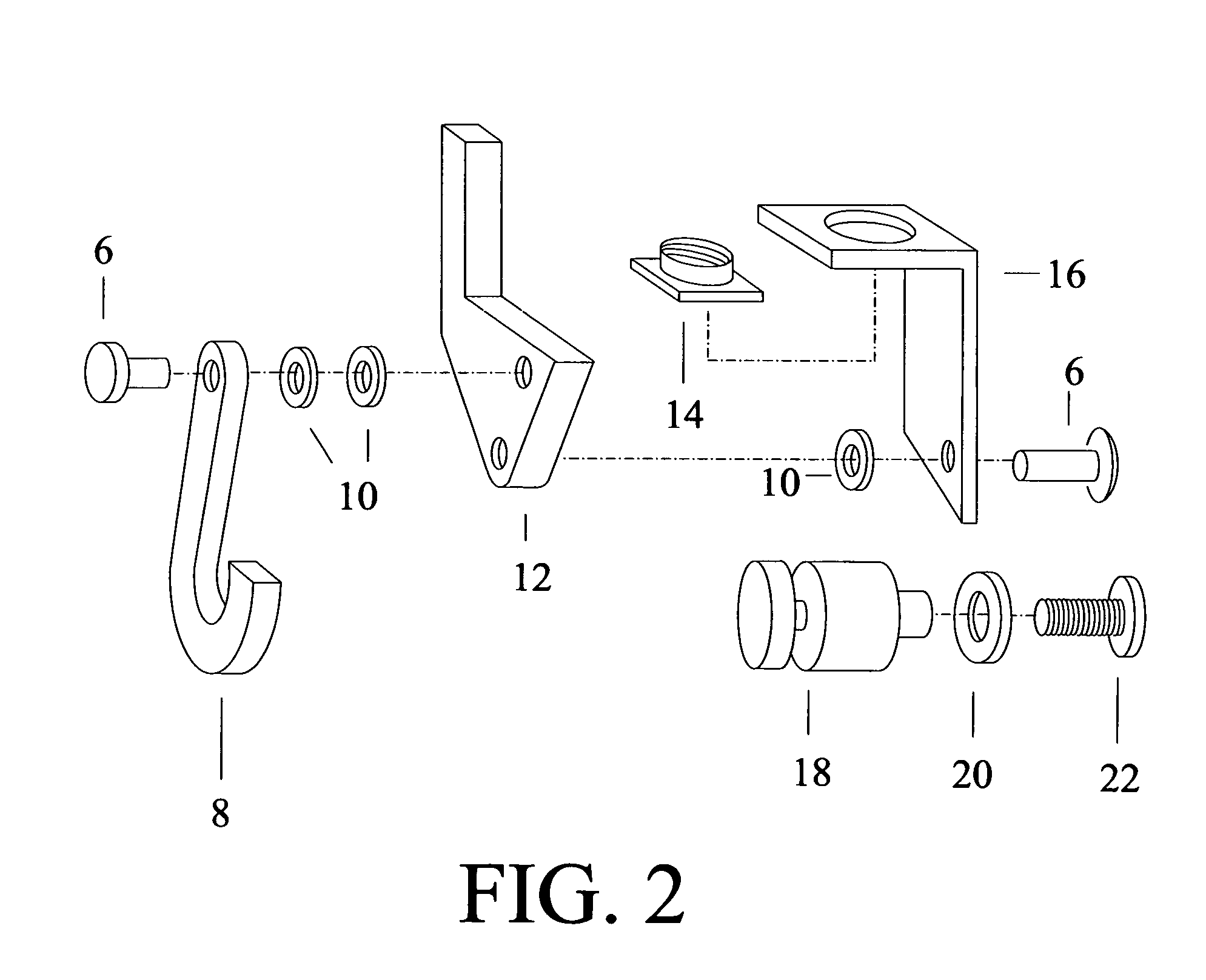
[0016]FIG. 2 provides an exploded view of the said apparatus and the corresponding anchor post 18. A fastener 6 connects the connecting arm 8 pivotally with release arm 12 spaced with spacers 10. The release arm 12 is then connected pivotally to the main body 16 with fastener 6 and space provided between them with a spacer 10. The lug nut 14 is placed through an opening from the underside of the flange of the main body 16.

[0017]FIG. 3 provides back schematic view of said apparatus with all parts assembled and in locked positi...


PUM


Abstract

A detachably connected drum tensioning apparatus for quickly and easily changing a drumhead (19) includes a main body (16) for holding a common drum lug nut (14), a release arm (12) pivotally connected to the main body (16), a connecting arm (8) pivotally connected to the release arm (12), and an anchor post which communicates with the connecting arm (8) is rigidly fixed to a drum shell.

Description

CROSS-REFERENCE TO RELATED APPLICATIONS [0001] This application claims the benefit of PPA Ser. No. 60 / 545,041, filed 2004 Feb. 17 by present inventor.BACKGROUND OF THE INVENTION [0002] 1. Field of Invention [0003] This invention relates to drum head tensioning devices specifically to such tensioning devices that are removable. [0004] 2. Prior Art [0005] The modern musical drum consists of a drum shell, head, rim, lug casings, lug nuts, and tensioning rods. Various numbers of lug casings are spaced and connected equidistance around the circumference of the cylindrical shape of the drum shell. The lug casings hold the lug nuts which receive the tensioning rods. The rim has holes made equidistance around its circumference to coincide with the number of lugs for a particular size drum. Tension rods are placed through these holes to connect with the lug nuts. A drumhead is stretched over the drum shell by the rim when the tension rods are tightened. The tension of the drumhead is adjuste...

Claims


Application Information

Patent Timeline
IPC IPC(8): G10D13/02
CPCG10D13/023G10D13/02G10D13/16
Inventor WHITTINGTON, JOEL THOMAS
Owner WHITTINGTON JOEL THOMAS
Why Eureka
Try Eureka