Drumhead assembly

a drumhead and assembly technology, applied in the field of drumheads, can solve the problems of complex production, substantial deafening of the drum, and the inability to achieve and achieve the effect of preserving the sound characteristics of the drum

Active Publication Date: 2010-08-24
RTOM CORP CORP
View PDF57 Cites 13 Cited by
  • Summary
  • Abstract
  • Description
  • Claims
  • Application Information

AI Technical Summary

Benefits of technology

[0012]These and other objects are achieved by the present invention which is directed to a drumhead assembly comprising a drumhead membrane fixed within an annular ring and a tensioning ring for tensioning the membrane, located within the annular ring and against the drumhead membrane, comprising a cylindrical rod formed in a circular, flat configuration and a tensioning member for maintaining the tensioning ring in a pre-tensioned configuration. The tensioning member can be adjustable, as in the form of a turnbuckle, so as to vary the diameter of the tensioning ring, or fixed, as in the form of a spacer, so as to maintain the tensioning ring at a predetermined diameter.
[0016]It is preferred that at least a portion of the connection member for connecting the practice drumhead assembly to the acoustic drum and / or drumhead be formed of an elastomeric material, and most preferably of rubber. The use of a connecting member formed at least in part of an elastomeric material is preferred to provide an easily removable means for connection of the practice drumhead assembly to the acoustic drum that will not interfere with or damage the drum. Most preferably, the entire engagement member, including the connection member, is formed of an elastomeric material.
[0018]As used herein, a “mesh” membrane refers to a permeable membrane, having an open weave with openings through which air can pass. This is the antithesis of a solid, acoustic or resonant membrane, as used in acoustic drumheads. The sound energy or volume of the output from a mesh membrane can be far less than the sound energy generated by an acoustic membrane. This reduced output from the mesh membrane allows the player to experience practice on a tensioned surface similar to that of the acoustic solid membrane drumheads with greatly reduced sound energy output.

Problems solved by technology

However, the foam or rubber disc eliminates the natural rebound of the drumstick striking a drumhead membrane and substantially deafens the tone of the drum.
As such, the tensioned device of U.S. Pat. No. 6,069,307 is complex and expensive to produce.

Method used


Image

  • Drumhead assembly
  • Drumhead assembly
  • Drumhead assembly

Examples


Embodiment Construction

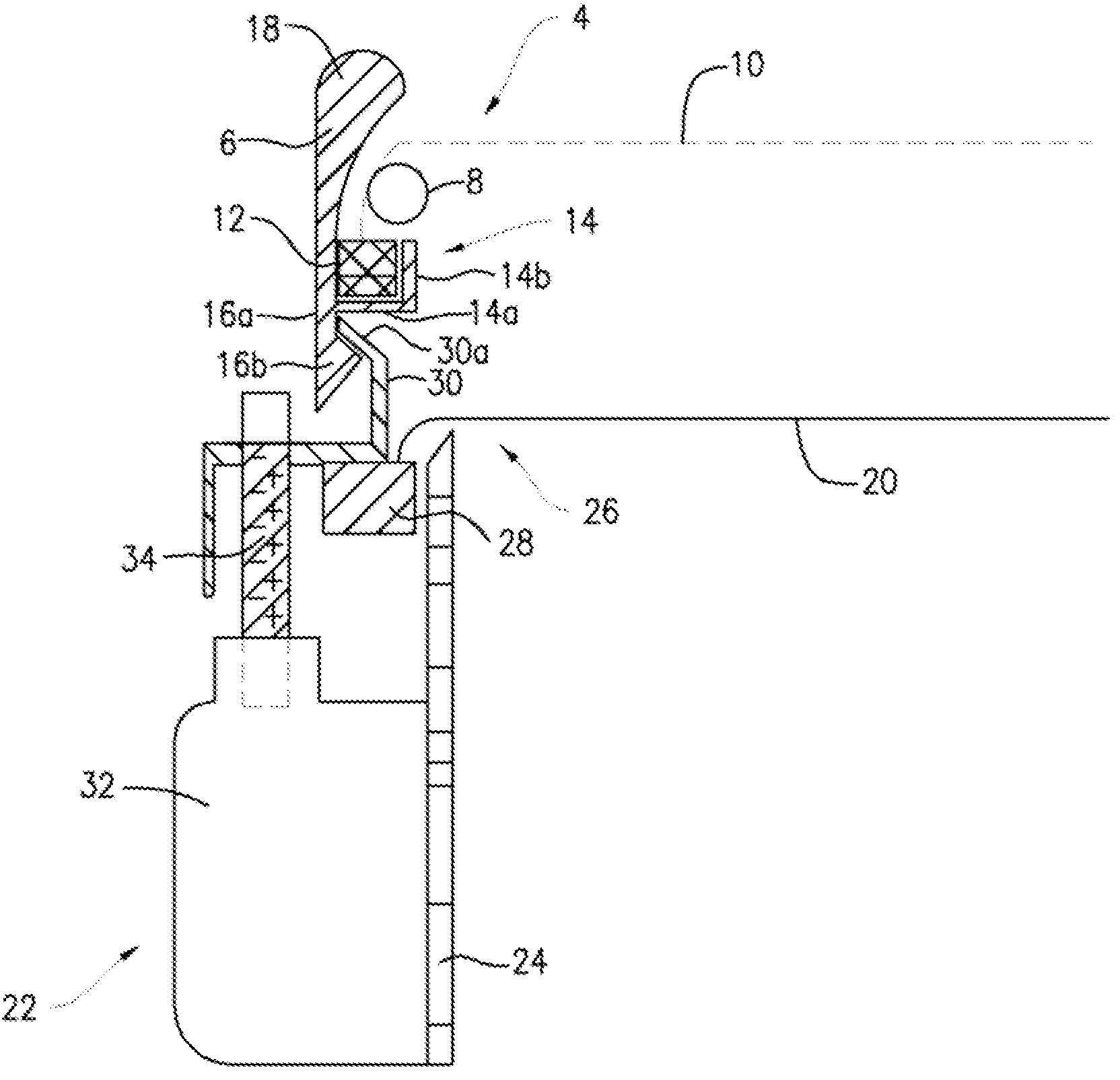
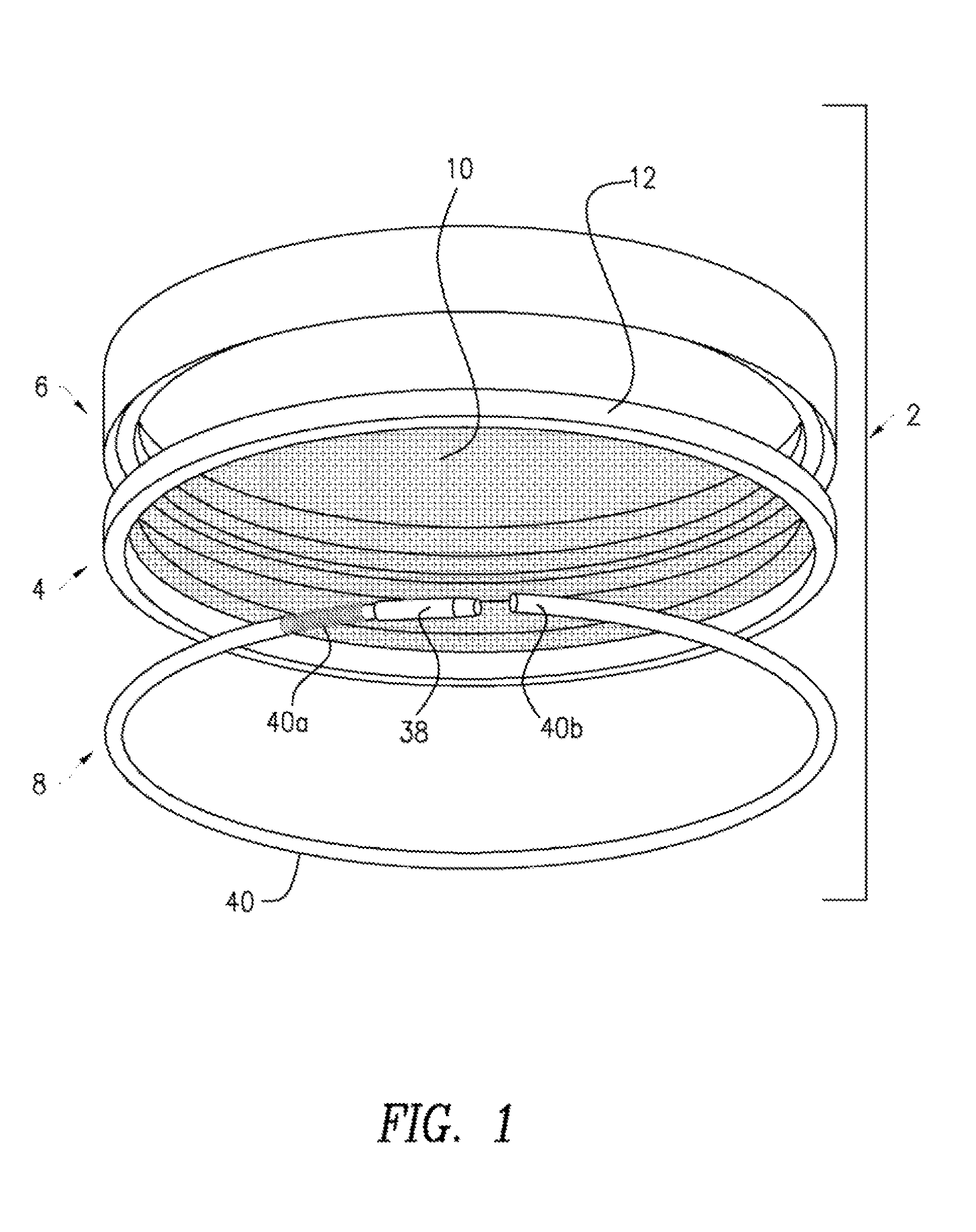
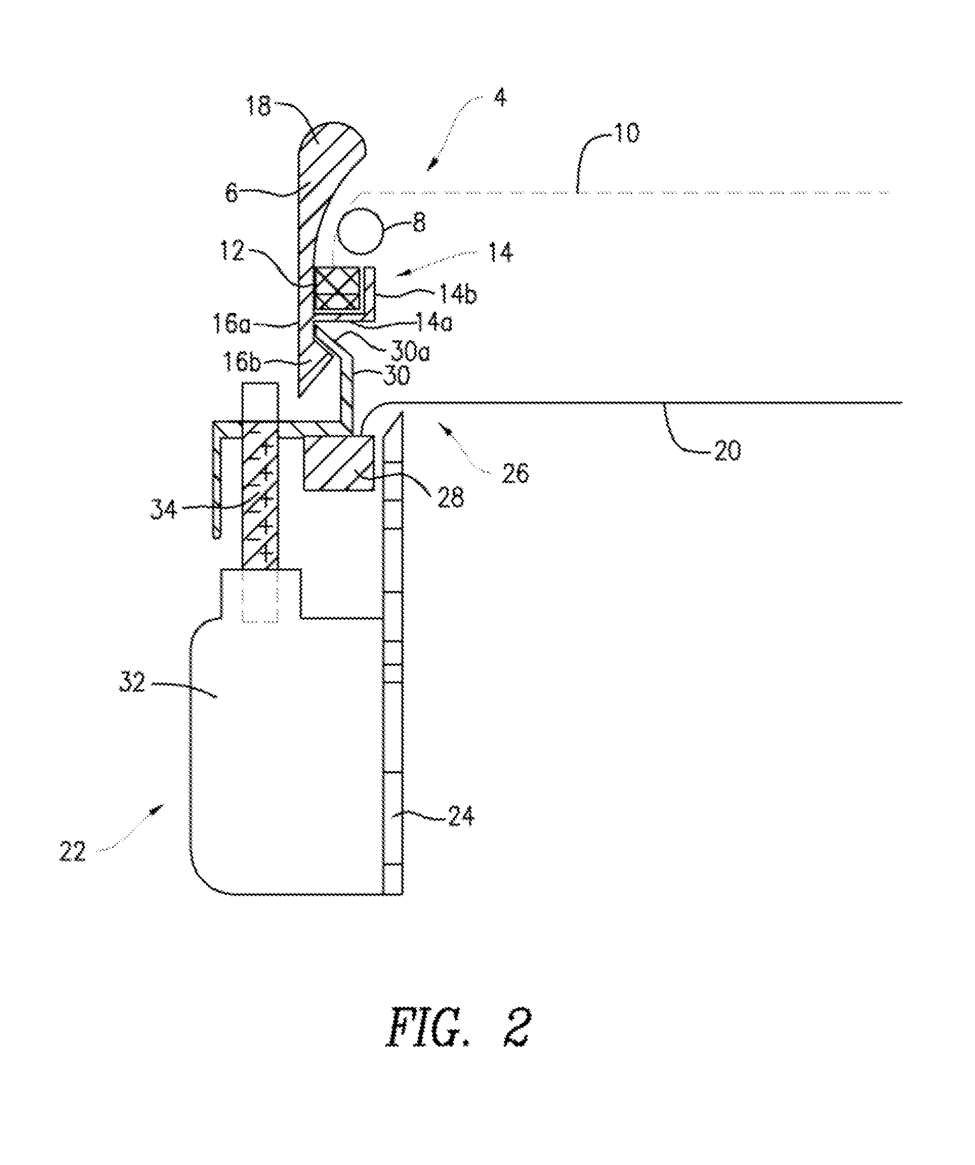
[0032]As shown in the drawings, and particularly FIG. 1, the present invention is directed to a drumhead assembly 2 comprising a mesh or practice drumhead 4, an engagement member 6 for maintaining the practice drumhead 4 in substantially fixed relation to an acoustic membrane and an annular tensioning ring 8 for creating tension across a mesh membrane 10 of the practice drumhead 4. The practice drumhead assembly 2 replicates the feel of an acoustic drumhead membrane but at a greatly reduced volume.

[0033]The mesh membrane 10 of the practice drumhead 4 is preferably locked into an annular frame 12 by means well known in the art of manufacturing drumheads, including such means as adhering the edge of the membrane 10 into the annular frame 12 with a resin or the like, clamping the edge of the membrane 10 in the annular frame 12, etc. Although the mesh membrane 10 can be fashioned of any suitable material known for making drumheads, having an open weave, a polyester material from about 5...


PUM


Abstract

A drumhead assembly comprising a drumhead membrane fixed within an annular ring and a tensioning ring for tensioning the membrane, located within the annular ring and against the drumhead membrane, comprising a cylindrical rod formed in a circular, flat configuration and a tensioning member for maintaining the tensioning ring in a pre-tensioned configuration. The tensioning member can be adjustable, as in the form of a turnbuckle, so as to vary the diameter of the tensioning ring, or fixed, as in the form of a spacer, so as to maintain the tensioning ring at a predetermined diameter.

Description

REFERENCE TO RELATED APPLICATIONS[0001]The present application is a continuation in part of U.S. patent application Ser. No. 11 / 335,114 filed on Jan. 19, 2006, now U.S. Pat. No. 7,514,617.FIELD OF THE INVENTION[0002]The present invention relates to the field of musical drums and more particularly to the field of drumheads comprising drum membranes held within annular rings having a tensioning ring within the annular ring and against the membrane.BACKGROUND OF THE INVENTION[0003]Musical drums are generally comprised of a shell and one or two tunable membranes locked into an annular frame, generally referred to as a drumhead, which is tensioned over the shell.[0004]To provide the proper tension to the drumhead, the shell has an arrangement of tensioning lugs attached to it, with threaded tension rods extending from the tensioning lugs. During installation the drumhead is placed over the shell and a counter hoop is placed over the annular frame of the drumhead. The tension rods engage ...

Claims


Application Information

Patent Timeline
Patent Type & Authority Patents(United States)
IPC IPC(8): G10D13/02
CPCG10D13/023G10D13/029G10D13/02G10D13/03G10D13/16
Inventor ROGERS, THOMAS P.GASTGEB, RAYMOND F.
Owner RTOM CORP CORP
Why Eureka
Try Eureka