Data recording disk drive with nonplanar plate surfaces for damping out-of-plane disk vibration

a technology of data recording disk and non-plane surface, which is applied in the direction of recording information storage, maintaining head carrier alignment, instruments, etc., can solve the cost of significantly increasing the torque of the spindle motor to rotate the disk stack, and achieve steady laminar air flow, reduce the torque of the spindle motor, and reduce the effect of viscous shear forces

Inactive Publication Date: 2005-09-01
HITACHI GLOBAL STORAGE TECH NETHERLANDS BV
View PDF7 Cites 29 Cited by
  • Summary
  • Abstract
  • Description
  • Claims
  • Application Information

AI Technical Summary

Benefits of technology

[0005] The invention is a disk drive with nonplanar damping plates that reduce spindle motor torque, as compared with planar damping plates, while maintaining steady laminar air flow at the disk stack perimeter. Each damping plate has a nonplanar surface that results in spacing between the stationary plate surface and its associated rotating disk surface that varies in the radial direction. In one embodiment the damping plate has a pattern of surface irregularities or features. The su

Problems solved by technology

The purely planar surfaces of the damping plates of the prior art reduce out-of-plane vibrations of the

Method used


Image

  • Data recording disk drive with nonplanar plate surfaces for damping out-of-plane disk vibration
  • Data recording disk drive with nonplanar plate surfaces for damping out-of-plane disk vibration
  • Data recording disk drive with nonplanar plate surfaces for damping out-of-plane disk vibration

Examples


first embodiment

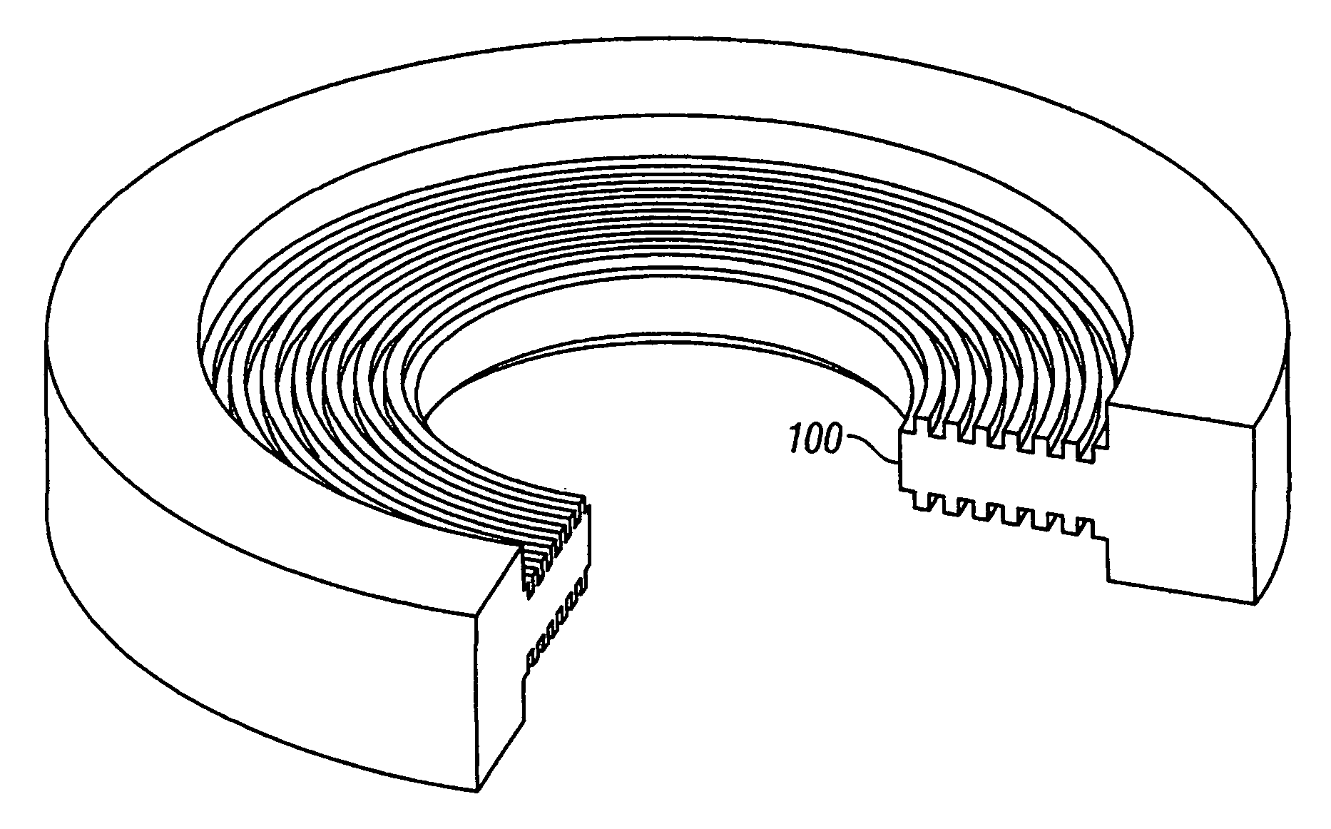
[0020]FIG. 4A is a perspective view and FIG. 4B a cross-sectional view of a damping plate 100 according to the present invention. Each of the two surfaces 102, 104 is a plurality of radially-spaced concentric grooves 110 separated by radially-spaced ribs 112. The grooves are depicted as being equally radially spaced, with each groove having a radial width wG and each rib a radial width wR. This design simplifies simulation of the air flow dynamics by selecting the ratio wG / wR to be one of the design variables. However, the advantages of the present invention are also achievable if the grooves are not equally radially-spaced and if the grooves do not all have the same depth or radial width. While the grooves in FIGS. 4A-4B have generally rectangular cross-sectional shapes, they may have other shapes, such as triangular, semicircular, etc.

[0021]FIG. 5 is a sectional view of the damping plate of FIGS. 4A-4B and a portion of its two associated axially-spaced disks 200, 250. Disk 200 has...

second embodiment

[0025]FIGS. 6A-6B illustrate a perspective view and cross-sectional view, respectively, of the damping plate in which the nonplanar surfaces have discrete surface features. The damping plate 300 has nonplanar surfaces 302, 304, each of which is a pattern of radially-spaced depressions or dimples arranged in concentric rings around plate 300. Each dimple has a shape with a circular perimeter, but the shape can take other forms, such as elliptical, hexagonal, etc. The dimples can have a depth approximately that of the grooves in the embodiment of FIGS. 4A-4B, i.e. 0.2 mm. Also, the surface features can be protuberances or bumps, instead of dimples. The bumps can have a height approximately that of the grooves in the embodiment of FIGS. 4A-4B, i.e. 0.2 mm. While the surface features are shown in FIGS. 6A-6B as patterned in concentric rings around the plate, they need not be located in such a pattern. However, it is believed that this pattern provides concentric rings of substantially p...

third embodiment

[0026]FIGS. 7A-7B illustrate a perspective view and cross-sectional view, respectively, of the damping plate. The damping plate 400 has nonplanar surfaces 402, 404, each of which is section of a conical surface. As shown by FIG. 7B the axial spacing S between each damping plate surface and its corresponding planar disk surface, such as between nonplanar surface 402 and planar surface 410 of disk 408, varies linearly (increasing or decreasing) in the radial direction r of the plate.

[0027] The invention has been described with application to a magnetic recording hard disk drive, but the invention is fully applicable to any data recording disk drive with hard disks, such as disk drives that read and / or write by one or more of magnetic, optical, thermo-magnetic and magneto-optic techniques.


PUM


Abstract

A data recording disk drive has damping plates with nonplanar surfaces for reducing flow-induced, out-of-plane vibration of the disks. The nonplanar damping plates reduce spindle motor torque, as compared with planar damping plates, while reducing the turbulent intensity. Each damping plate has a nonplanar surface that results in spacing between the plate surface and its associated disk surface that varies in the radial direction. The nonplanar surface may be a pattern of surface irregularities or features that may be arranged in concentric patterns, such as a pattern of concentric grooves, depressions or protuberances. The nonplanar surface may be shaped as a section of a conic surface so that in the radial direction the spacing between the damping plate surface and its associated disk surface varies linearly. For the disk surfaces facing the top and bottom of the disk housing, the nonplanar surfaces are applied to the top and bottom of the disk housing. Thus, in the single disk case, no separate damping plate is needed.

Description

TECHNICAL FIELD [0001] This invention relates generally to data recording disk drives, such as magnetic recording hard disk drives, and more specifically to such disk drives with damping plates for reducing flow-induced out-of-plane disk vibration as well as flow-induced arm and suspension vibration. BACKGROUND OF THE INVENTION [0002] Data recording disk drives have a stack of recording disks rotated by a spindle motor, and an actuator that moves the read / write heads across the surfaces of the rotating disks. Each read / write head is formed on an air-bearing slider attached to one end of a suspension. The suspension is attached at its other end to a rigid arm of the actuator and allows the slider to pitch and roll on a bearing of air generated by the rotating disk. The trend in future disk drives is a continual decrease in the spacing of the data tracks to increase the data storage density, and a continual increase in the rotational speed of the disk stack to decrease the data transf...

Claims


Application Information

Patent Timeline
IPC IPC(8): G11B5/55G11B5/596G11B33/00G11B33/08G11B33/14
CPCG11B5/5565G11B33/08G11B5/59627
Inventor CHAN, ANDRE S.HENDRIKS, FERDINANDHIRANO, TOSHIKIKESHAVAN, MANOJ
Owner HITACHI GLOBAL STORAGE TECH NETHERLANDS BV
Why Eureka
Try Eureka