Method and apparatus for analyzing bioelectrical response waveform information, and diagnostic apparatus thereof

a bioelectric response waveform and information technology, applied in the field of bioelectric response waveform information analysis methods and diagnostic equipment thereof, can solve the problems of low precision, low precision, bp instability, etc., and achieve the effect of facilitating efficient primary prophylaxis

Inactive Publication Date: 2005-09-01
OHKURA TAMIKO
View PDF4 Cites 12 Cited by
  • Summary
  • Abstract
  • Description
  • Claims
  • Application Information

AI Technical Summary

Benefits of technology

[0023] Furthermore, since the present invention enables noninvasive prediction of diseases, it is especially effective when applie...

Problems solved by technology

Therefore, BP has instability and a low precision and varies greatly due to personal differences and conditions of the measuring environment (especially seaso...

Method used


Image

  • Method and apparatus for analyzing bioelectrical response waveform information, and diagnostic apparatus thereof
  • Method and apparatus for analyzing bioelectrical response waveform information, and diagnostic apparatus thereof
  • Method and apparatus for analyzing bioelectrical response waveform information, and diagnostic apparatus thereof

Examples


embodiment 1

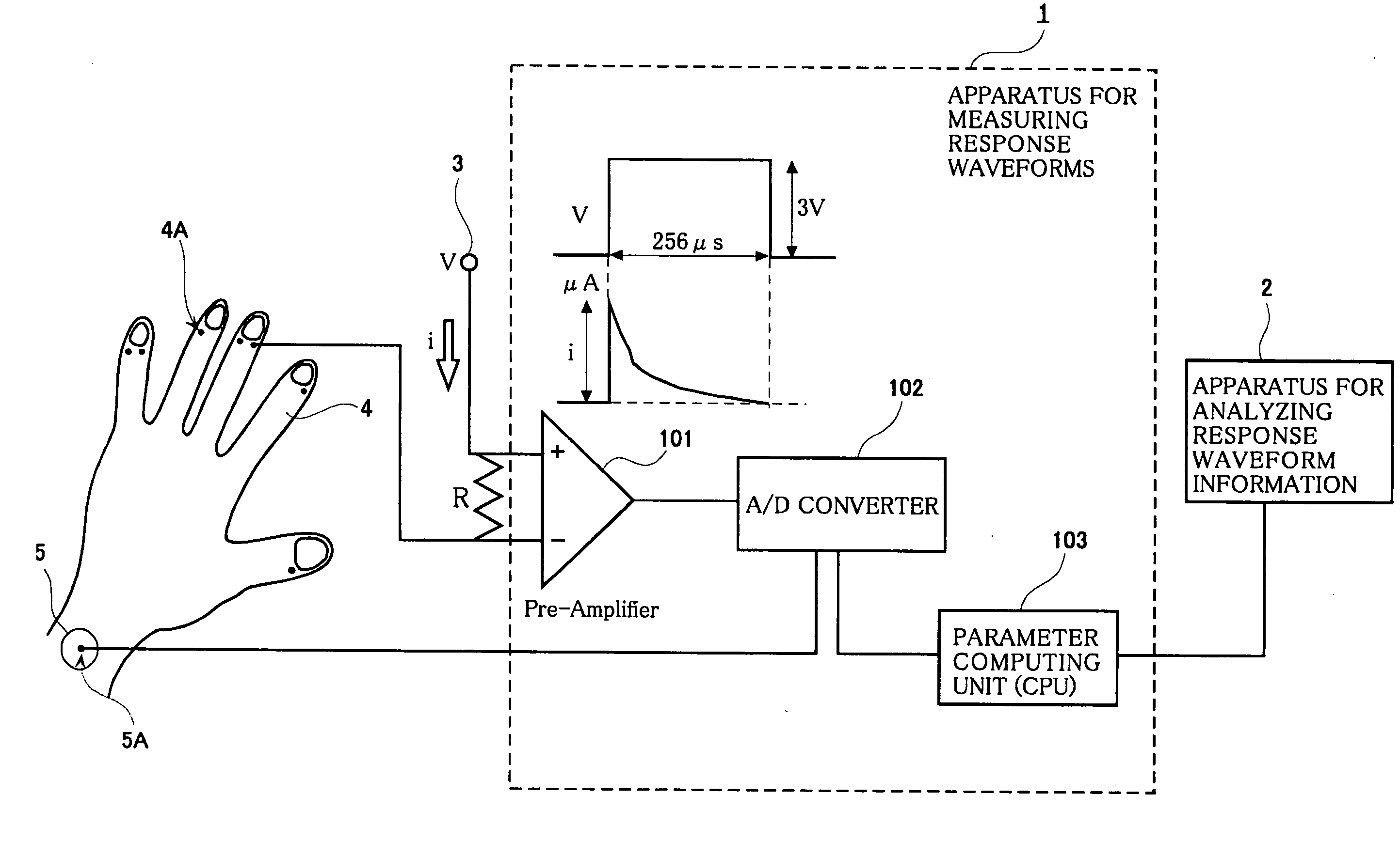
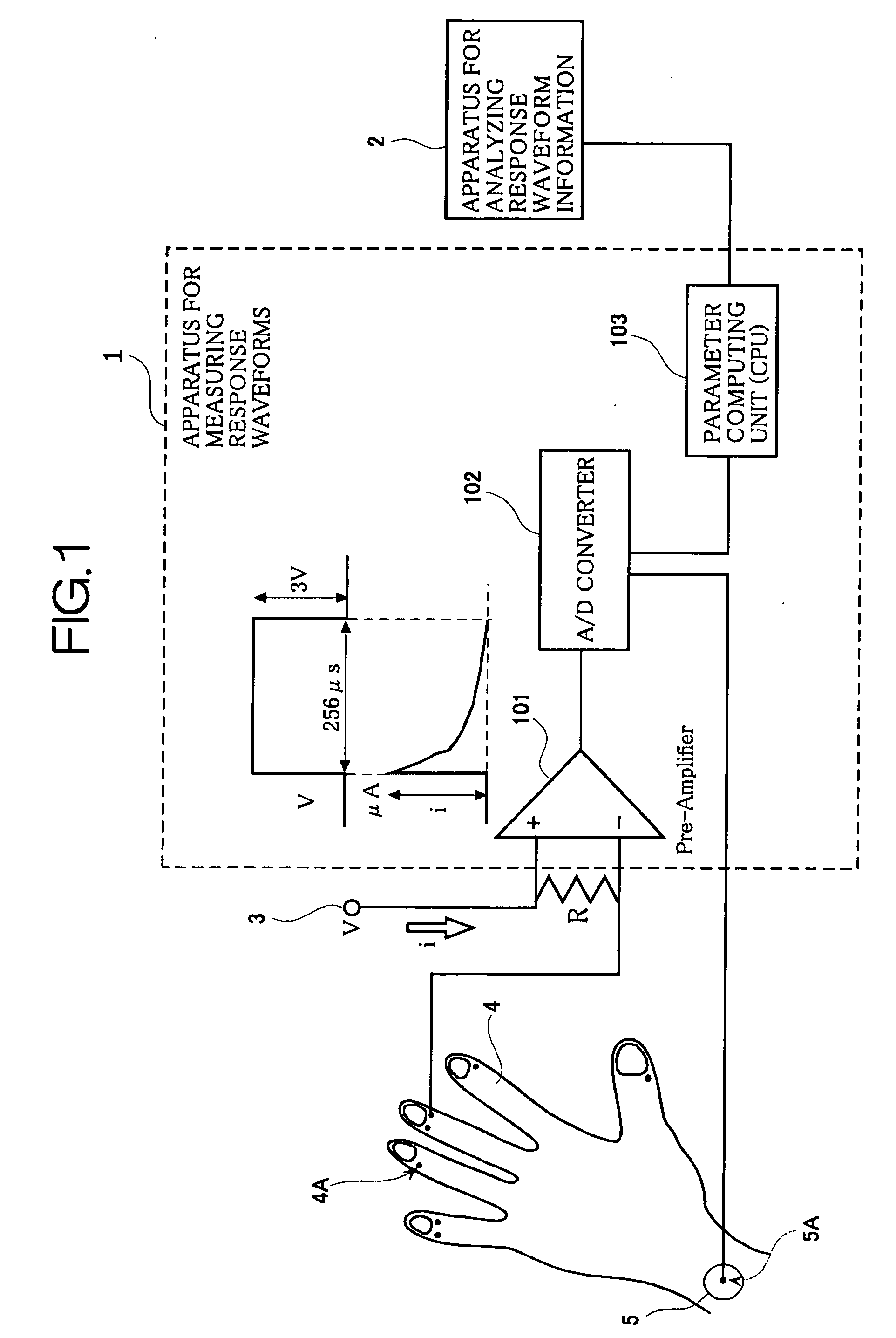
[0047]FIG. 1 is a functional block diagram of an apparatus for measuring bioelectrical response waveforms according to an embodiment (implementation) 1 of the present invention.

[0048] As shown in FIG. 1, the apparatus for measuring bioelectrical response waveforms 1 according to the embodiment 1 includes a current amplifier (Pre-Amplifier) 101, an A / D converter 102, and parameter computing means (CPU) 103.

[0049] For example, the apparatus for measuring bioelectrical response waveforms 1 according to the embodiment 1 has a silver-gel different electrode 4A of 7 mm square attached to a meridian point on a finger 4, and a dish-shaped electrode (indifferent electrode for electrocardiograms) 5A attached to a wrist 5. A pulse voltage V (e.g., a pulse voltage of 3 volts with a cycle period of 256 μs) is applied with a predetermined cycle period (e.g., a frequency of 1 MHz) by a power supply 3 through a resistor R. This allows a polarization current (μA) to flow between the silver-gel dif...

embodiment 2

[0075]FIG. 8 is a functional block diagram of an apparatus for analyzing and diagnosing bioelectrical response waveform information according to an embodiment (implementation) 2 of the present invention.

[0076] In FIG. 8, reference numeral 1 denotes an apparatus for measuring response waveforms (apparatus for measuring bioelectrical (skin) impedance), reference numeral 2 denotes the apparatus for analyzing and diagnosing bioelectrical (skin) response waveform information, and reference numeral 212 denotes a data output apparatus.

[0077] As shown in FIG. 8, the apparatus for analyzing and diagnosing bioelectrical response waveform information 2 according to the embodiment (implementation) 2 includes: a keyboard 201 for inputting a measured person's properties (a measured person's property input means); a data buffer 202 for storing the three parameter information items of values ES, IS, and NT that are input by the apparatus for measuring response waveforms; storage 203 such as semic...


PUM


Abstract

A method for analyzing skin response waveform information obtained by measuring skin impedance with a voltage of a predetermined frequency. A current value at the start of polarization caused by the application of the voltage is determined, followed by determining a current value after a predetermined amount of time from the start of the polarization. A current value after termination of the polarization (value NT) is then determined and the difference between the current value at the start of the polarization and after the predetermined amount of time from the start of the polarization (value A) is determined. The difference between the current value after the predetermined amount of time from the start of the polarization and the value NT (value B) is determined, followed by analyzing the skin response waveform information using the ratios A/B, B/A and the value NT.

Description

CROSS-REFERENCE TO RELATED APPLICATION [0001] This application is a continuation-in-part of U.S. application Ser. No. 10 / 468,805 entitled “Method AND APPARATUS FOR ANALYZING BIOELECTRICAL RESPONSE WAVEFORM INFORMATION, AND DIAGNOSTIC APPARATUS THEREOF” and filed on Mar. 4, 2004, by Tamiko OHKURA, the contents of which are herein incorporated by reference, which application is a 371 of PCT / JP02 / 01864 filed on Feb. 28, 2002, and claims priority benefits of Japanese Patent Application No. 2001-56298 filed Mar. 1, 2001.TECHNICAL FIELD [0002] The present invention relates to a method and apparatus for analyzing skin response waveform information obtained by measuring skin impedance with a voltage of a predetermined frequency, as well as an apparatus for performing a diagnosis on a body using the method and apparatus. More particularly, the invention relates to a technique for performing an analysis with three parameters of values ES, IS, and NT of the response waveform information, as we...

Claims


Application Information

Patent Timeline
IPC IPC(8): A61B5/053
CPCA61B5/0531
Inventor OHKURA, TAMIKO
Owner OHKURA TAMIKO
Why Eureka
Try Eureka