Locking astragal with self positioning seal

Inactive Publication Date: 2005-09-08
SANDERS VERNARD W
View PDF26 Cites 21 Cited by
  • Summary
  • Abstract
  • Description
  • Claims
  • Application Information

AI Technical Summary

Benefits of technology

[0048] For the foregoing reasons, there is a need for a self positioning astragal seal that prevents unwanted drafts, is easy to use and install in a quick, convenient, and efficient manner, is durable and long lasting, maintains its seal against drafts over time, even in situations where repeated opening and closing of the inactive door is necessary, and can be used with a variety of astragals and threshold sills, types, sizes, and shapes of threshold sills, doors, and door frames. The self positioning astragal seal should be capable of automatically positioning at least one seal at the lower end of the astragal adjacent the threshold sill, and prevent drafts at the vicinity of the lower end of the astragal and the threshold sill, and/or of automatically positioning at least one seal at the upper end of the astragal adjacent the header, and prevent drafts at the vicinity of the header. The self positioning astragal seal should independently position itself abuttingly adjacent the sill and/or the header when the bolts are extended from a retracted position to an extended position and are received by the upper and/or lower apertures in the upper and/or lower portions of the door frame. The astragal should also have a lock for locking the bolts into the extended position, and unlocking the bolts at a user's discretion, thus, provide additional security.
[0049] Th

Problems solved by technology

Since many different types, sizes, and shapes of thresholds are used, the drafts remain an unwanted by product of using the stationary sills.
In many instances, the fixed size of the seals, and the materials used, for the stationary seals, are either too thick or too thin to fill the gap between the lower end of the astragal and the thre

Method used


Image

  • Locking astragal with self positioning seal
  • Locking astragal with self positioning seal
  • Locking astragal with self positioning seal

Examples


Example

REFERENCE NUMERALS

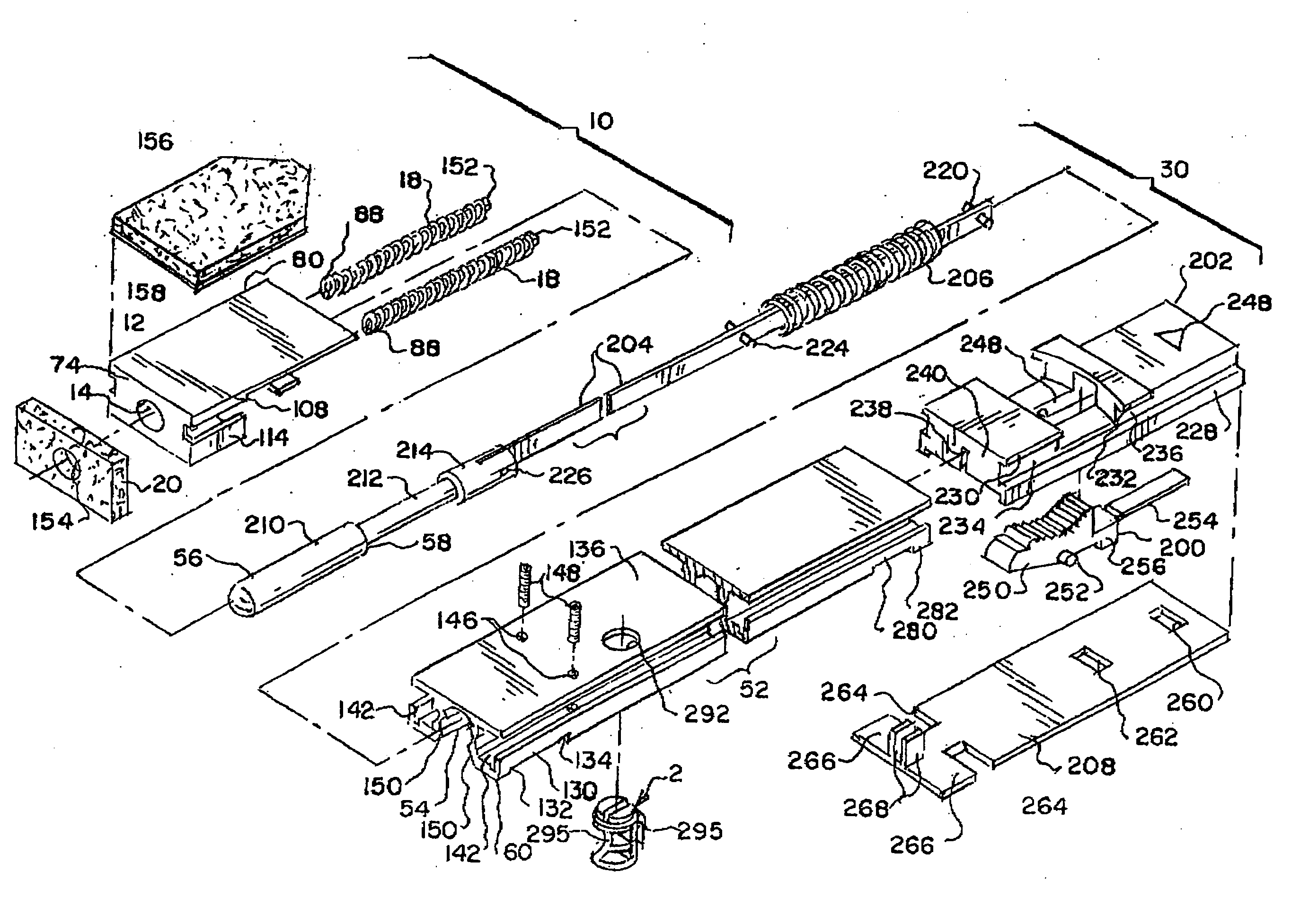
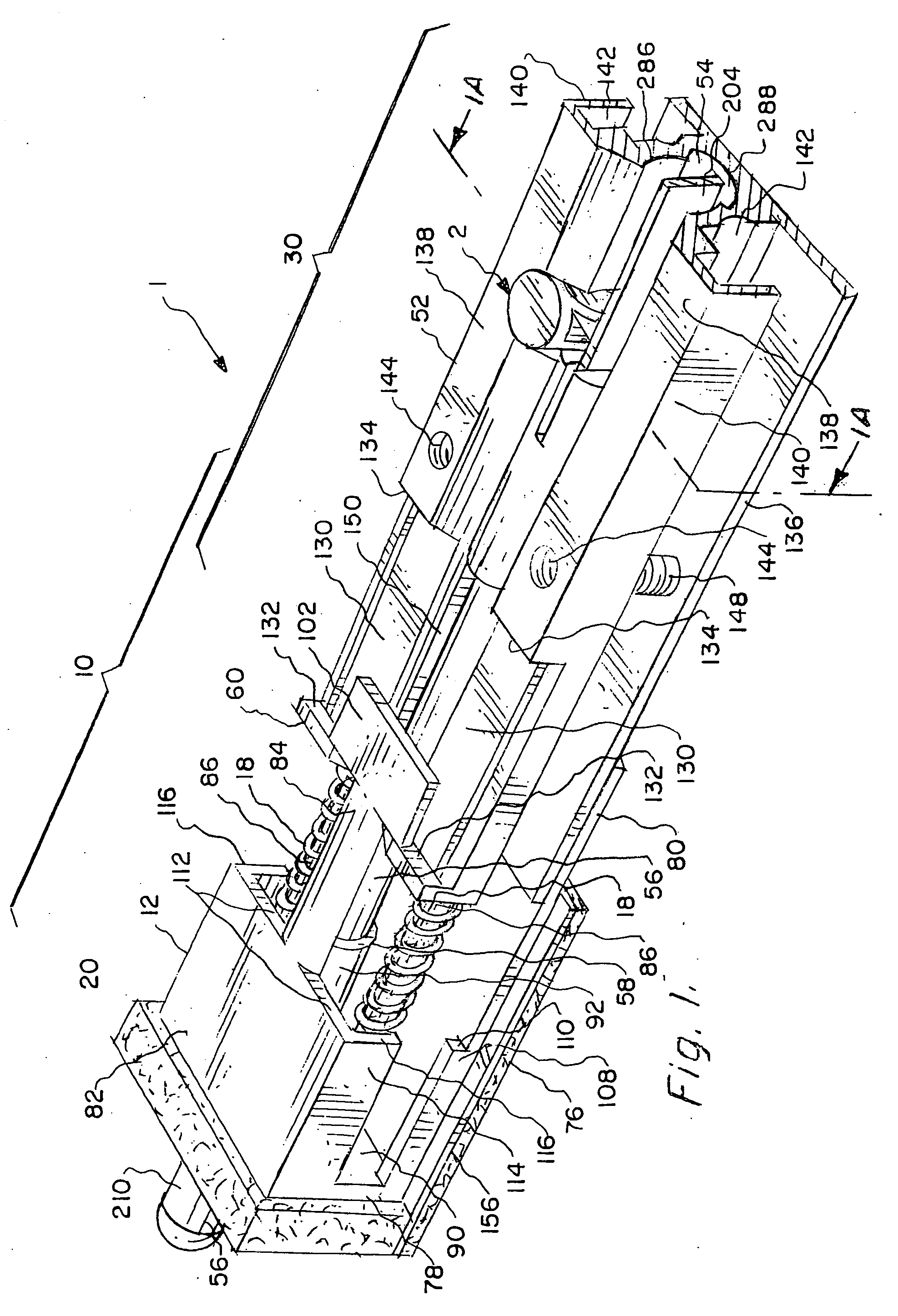
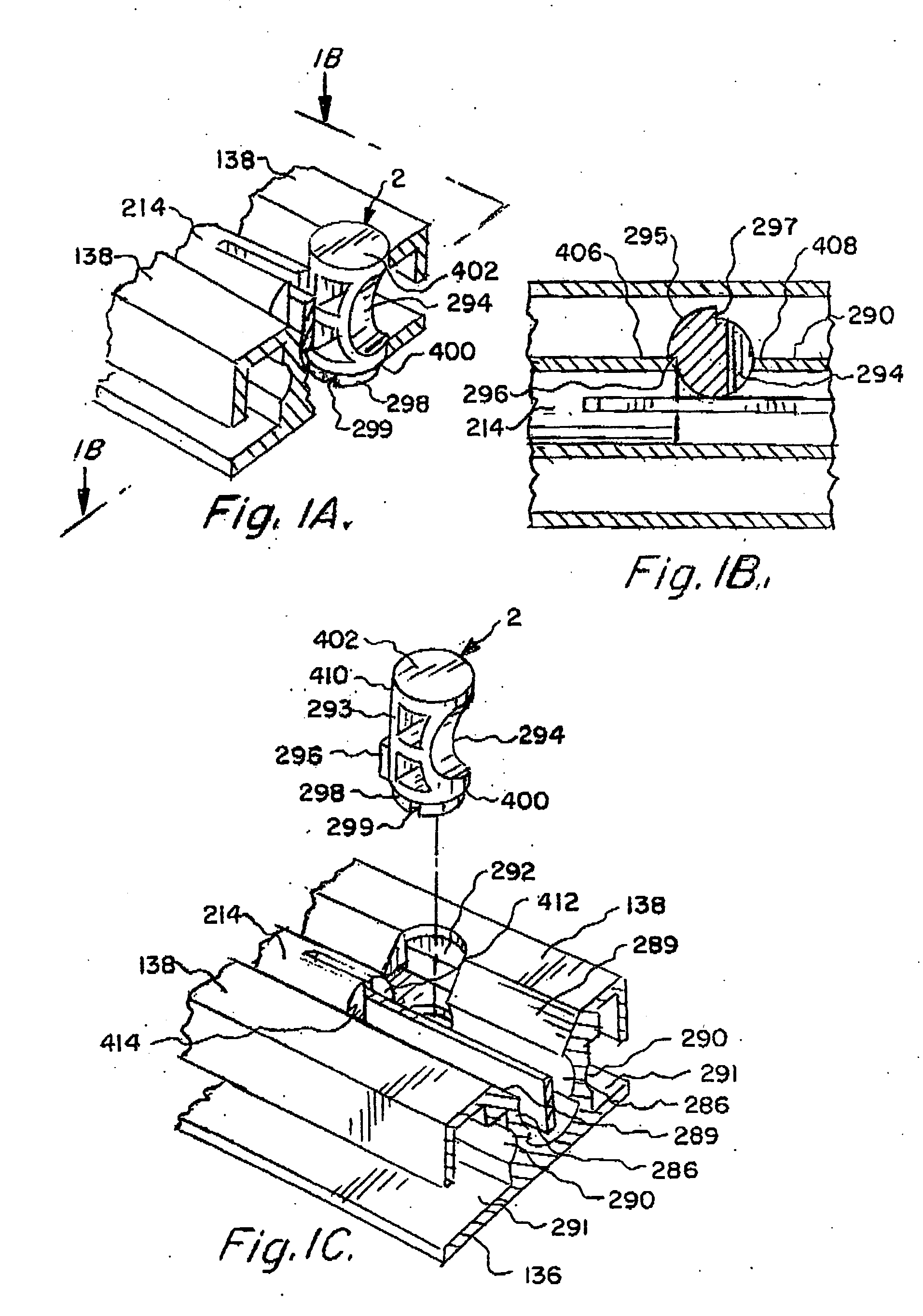
[0094] These and other features, aspects, and advantages of the present invention will become better understood with regard to the references and associated reference numerals of the following description and accompanying drawings where: [0095]1 locking astragal with self positioning astragal seal [0096]2 lock [0097]10 self positioning astragal seal [0098]12 seal block [0099]14 seal block hole [0100]16 shoulder [0101]18 compression spring [0102]20 end seal [0103]30 astragal [0104]42 inactive door edge [0105]44 inactive door [0106]46 sill [0107]48 door frame [0108]52 elongated guide [0109]54 elongated guide channel [0110]56 lower bolt [0111]58 shoulder [0112]60 astragal bottom [0113]74 seal block bottom [0114]78 seal block base [0115]80 face plate [0116]82 guide block [0117]84“T” shaped member [0118]86 compression spring guide holder [0119]88 compression spring bottom end [0120]90 base top [0121]92 barrel [0122]94 barrel extension [0123]96 barrel extension arcuate ...


PUM


Abstract

A locking astragal with self positioning seal that automatically positions at least one seal at the lower end of an astragal adjacent the threshold sill of a door frame, and prevents drafts at the vicinity of the lower end of the astragal and the threshold sill, and/or automatically positions at least one seal at the upper end of the astragal adjacent the header of the door frame, and prevent drafts at the vicinity of the header. The self positioning seal independently positions itself abuttingly adjacent the sill and/or the header when the astragal's bolts are extended from a retracted position to an extended position and are received by the upper and/or lower apertures in the upper and/or lower portions of the door frame, the astragal having locks for locking the bolts into the extended position, and can be used with a variety of thresholds, sills, headers, doors, and door frames

Description

[0001] This application is a continuation-in-part of U.S. patent application Ser. No. 10 / 763,091, filed Jan. 21, 2004, which claims the benefit of provisional Application No. 60 / 441,797, filed Jan. 21, 2003.BACKGROUND OF THE INVENTION [0002] 1. Field of the Invention [0003] The present invention relates generally to locking astragals and more particularly to locking astragals with self positioning seals. [0004] 2. Background Art [0005] Double entrance doorways are used in a large variety of residential homes and commercial buildings. Typically, an active door provides for day to day ingress and egress to and from the residential home or building, and an inactive door remains closed, except in instances when a width greater than or equal to the width of the active door and less than or equal to the width of the double entrance doorway is required, such as, for example, for delivery of furniture and / or equipment that cannot fit through the double entrance doorway. If large objects, su...

Claims


Application Information

Patent Timeline
IPC IPC(8): E06B3/36E06B7/215
CPCE06B7/215E06B3/365Y10T70/5221
Inventor SANDERS, VERNARD W.
Owner SANDERS VERNARD W
Why Eureka
Try Eureka