Grooved pyramid disperger plate

a pyramidal, disperger plate technology, applied in the field of dispergers, can solve the problems of limiting reducing the number of dispergers, and reducing the efficiency of the removal process

Active Publication Date: 2005-09-08
ANDRITZ INC
View PDF10 Cites 34 Cited by
  • Summary
  • Abstract
  • Description
  • Claims
  • Application Information

AI Technical Summary

Benefits of technology

[0010] Each of the teeth also has oppositely disposed leading and trailing edges. The leading and trailing edges of each tooth of the plate carried by the first disc create an intersection with the leading and trailing edges of Is corresponding teeth of the plate carried by the second dis...

Problems solved by technology

The removal processes are not completely efficient and the residual ink, toner and stickies must be dispersed or else the stickies adhere to parts of the paper machine and cause holes or we...

Method used


Image

  • Grooved pyramid disperger plate
  • Grooved pyramid disperger plate
  • Grooved pyramid disperger plate

Examples


Embodiment Construction

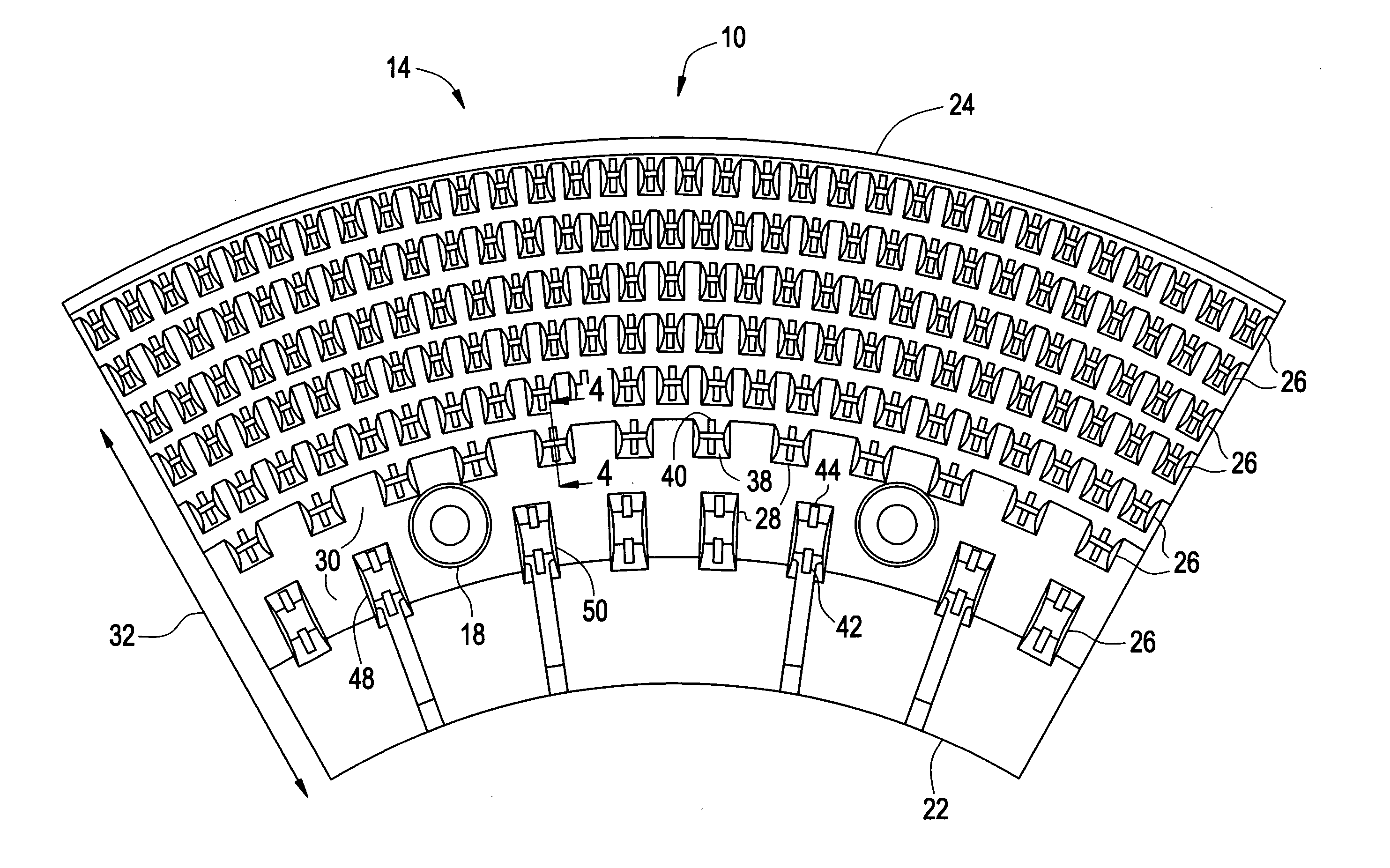
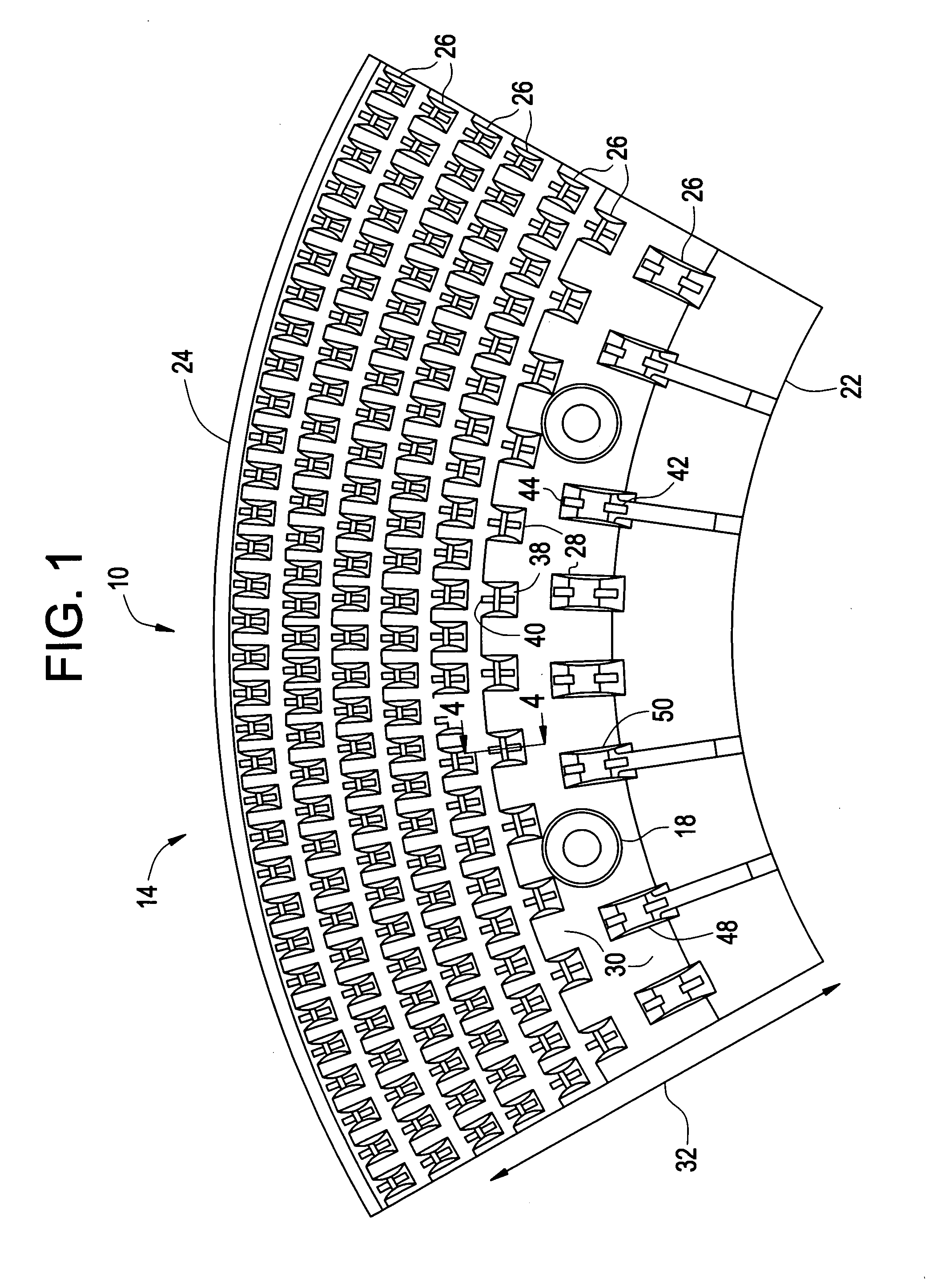
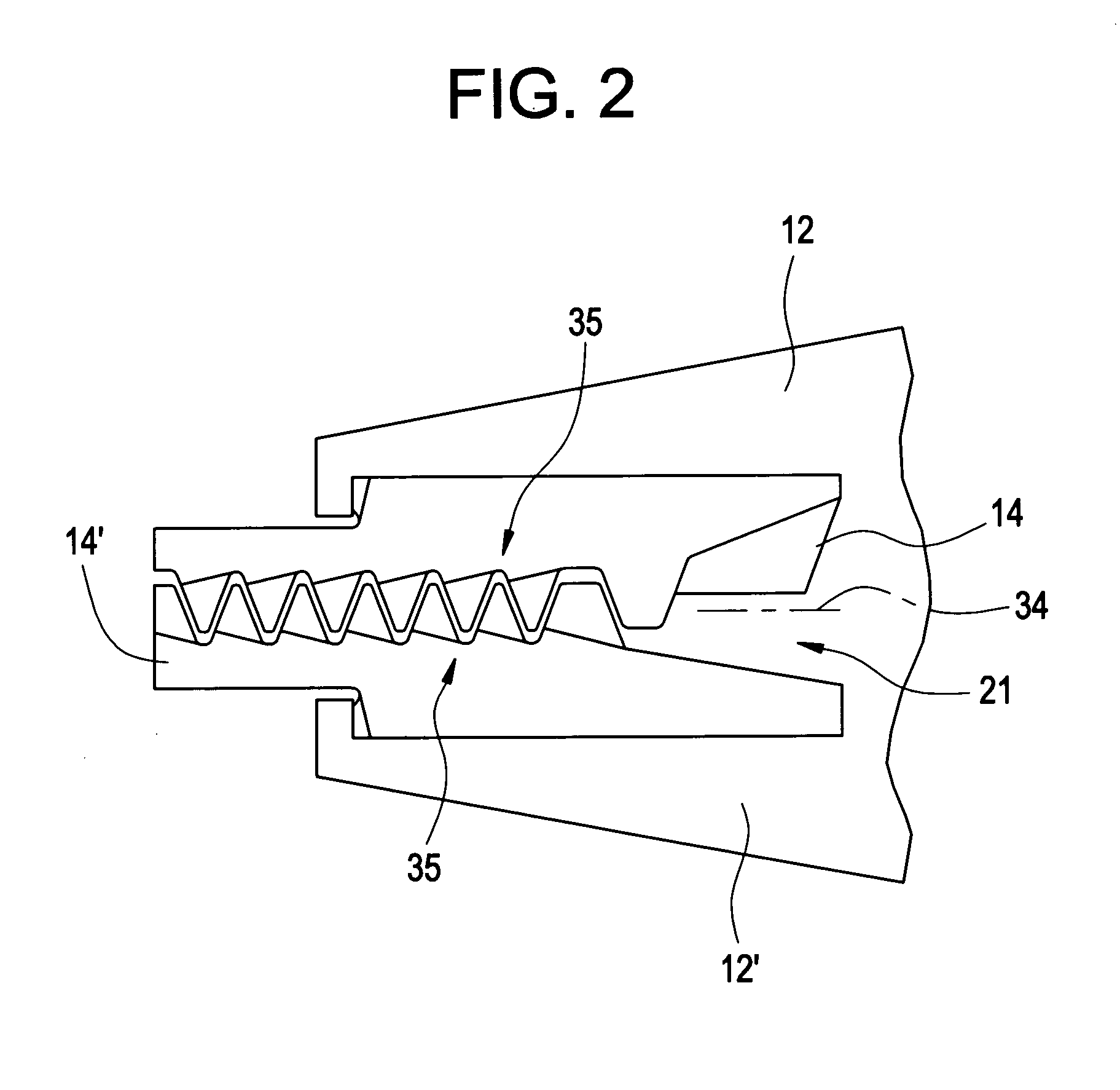
[0016] With reference to the drawings wherein like numerals represent like parts throughout the several figures, a portion of a substantially circular disperger plate in accordance with the present invention is generally designated by the numeral 10. Generally, a disperger has two circular discs facing each other with one disc (the rotor) 12 being rotated at up to 1800 rpm. The other disc (the stator) 12′ is stationary. Alternatively, both of the discs 12, 12′ may be rotors.

[0017] With reference to FIGS. 1 and 2, the portion 10 comprises a disperger plate segment 14, 14′ which is securable to the face of one of the disperger discs 12, 12′. Although in the illustrated embodiment the portion 10 is a unitary segment, each portion 10 could alternatively be provided as two or more segments.

[0018] The plate segment 14, 14′ is attached to the disc face 16, in any convenient or conventional manner, such as by bolts (not shown) passing through bores 18. Typically, one end of the bolt engag...


PUM

PropertyMeasurementUnit
Lengthaaaaaaaaaa
Angleaaaaaaaaaa

Abstract

A disperger plate segment, for removing contaminants from recycled, or recovered, paper and packaging materials includes radially concentric rows of teeth. Each row of teeth includes teeth and channels disposed intermediate the teeth. Each of the teeth have an upper, top surface, a radially inner face extending from the channel base surface to the tooth top surface, and a radially outer face extending from the channel base surface to the tooth top surface. The teeth inner and outer faces each have a groove extending from the tooth top surface to a position intermediate the tooth top surface and the channel base surface.

Description

CROSS-REFERENCE TO RELATED APPLICATIONS [0001] This application claims the benefit under 35 U.S.C. § 119(e) of U.S. Provisional Patent Application Ser. No. 60 / 542,126 filed Feb. 5, 2004.BACKGROUND OF THE INVENTION [0002] This invention relates generally to dispergers for removing contaminants from recycled, or recovered, paper and packaging materials. More particularly, the present invention relates to disperger plate segments for use in such apparatus. [0003] Recovered paper and packaging materials are subjected to several processes designed to remove ink, toner in the case of copy paper, and contaminants such as plastics generally referred to as “stickies”. The removal processes are not completely efficient and the residual ink, toner and stickies must be dispersed or else the stickies adhere to parts of the paper machine and cause holes or weak spots in new paper. Residual ink particles appear as specs in the reconstituted paper lowering its value considerably. [0004] A machine c...

Claims


Application Information

Patent Timeline
IPC IPC(8): B02C1/00D21B1/08D21B1/30D21B1/32D21C1/00D21C5/02D21C9/00D21D1/30D21D5/00
CPCD21B1/32D21D1/30D21D1/008Y02W30/64
Inventor CASSIDY, DANNY
Owner ANDRITZ INC
Why Eureka
Try Eureka