Submarine pipeline spoiler

a technology for submerged pipelines and spoilers, which is applied in the direction of valves, mechanical equipment, valve operation/release devices, etc., can solve the problems of long time for self-burying, and inability to bury pipelines at sea

Inactive Publication Date: 2005-09-15
EDFELDT MICHAEL PAUL
View PDF4 Cites 18 Cited by
  • Summary
  • Abstract
  • Description
  • Claims
  • Application Information

AI Technical Summary

Benefits of technology

[0014] The apparatus may comprise a seat and fin structure secured to a pipeline such as via metal straps. The spoiler seat further may provide for piggy-backing of a second pipeline or cable.

Problems solved by technology

A smooth and circular conduit often has a tendency toward self-burial, but the effect often is insufficient, so that the conduit is easily exposed again and / or the time for self-burying is very long, with the inherent danger of damage by anchors, fishing gears or the like.
These traditional methods of burying conduits suffered from numerous problems, including, but not limited to, adverse environmental impact and cost.

Method used


Image

  • Submarine pipeline spoiler
  • Submarine pipeline spoiler
  • Submarine pipeline spoiler

Examples


second embodiment

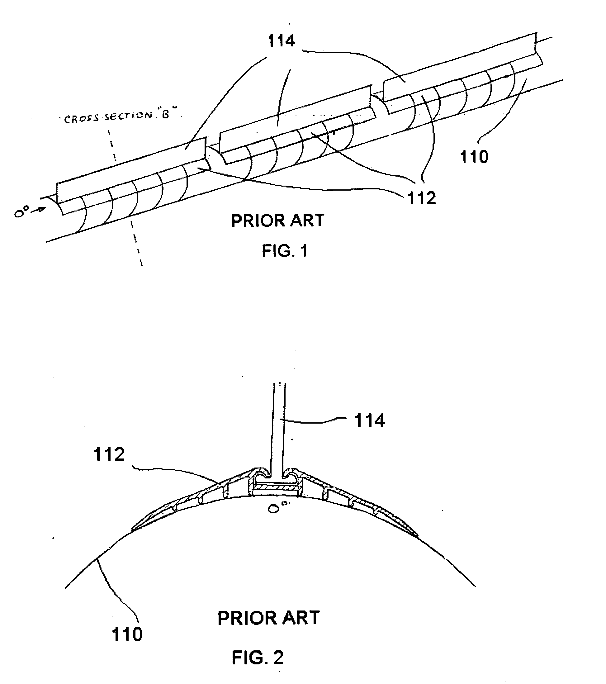
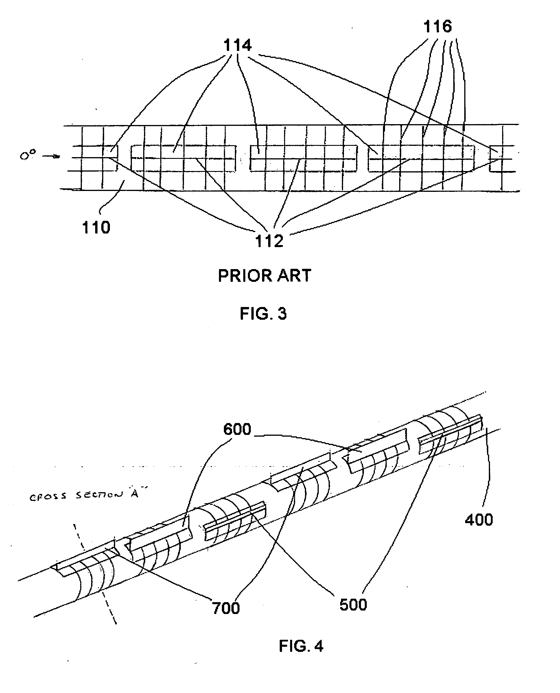
[0038] In a second embodiment, the present invention is incorporated by way of a new seat template as shown in FIG. 9. This new seat template has three grooves for receiving fins. In FIG. 9, the grooves are spaced radially by 20 degrees, but in practice may be spaced at other radial intervals as desired. It likewise is possible to provide two or more than three groove radially spaced on the seat. With a triple seat of the type shown in FIG. 9, one can achieve the alternating fin placement shown in FIG. 4 using the same triple seat design for each spoiler and placing the fins in the various grooves in the seat.

third embodiment

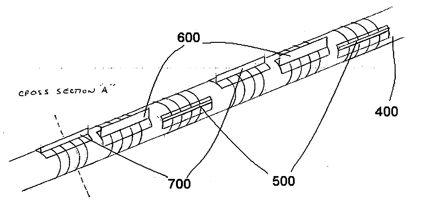
[0039] In a third embodiment, a piggy-back seat structure such as is shown in FIG. 10 may be incorporated into a triple seat such as is shown in FIG. 9 to provide for both piggy-backing of a pipe on top of the pipeline and for alternating fin placement as shown in FIG. 4. Such a triple piggy-back seat is shown in FIG. 11. The triple piggy-back seat has three grooves 214 for receiving fins 300, with the grooves being spaced radially by 20 degrees. The seat further has inner side members 216 forming a concave portion for receiving the piggy-back pipe 222, outer side members 220, and support members 218. The grooves, of course, may be spaced radially at angles different than 20 degrees. Likewise, more grooves could be used if such was desirable for particular environmental conditions. Further, other structures of support members, outer sides, and inner sides may be used.

[0040]FIG. 12 is a graph of the hydrodynamic coefficients as a function of spoiler height. This graph generally shows...


PUM


Abstract

A method and apparatus for stabilizing and burying a conduit in a waterbed is disclosed. A plurality of spoilers are placed on the conduit at longitudinally and radially different positions to promote self-burial, reduce vortex-induced vibration, prevent upheaval buckling, minimize future corrective work by continuous reburial of the under water conduit or pipeline.

Description

CROSS-REFERENCE TO RELATED APPLICATIONS [0001] None. STATEMENT REGARDING FEDERALLY SPONSORED RESEARCH OR DEVELOPMENT [0002] Not applicable. FIELD OF THE INVENTION. [0003] The present invention relates to the field of burying underwater pipelines, and more specifically to a method and device for promoting self-burial and / or stabilization of underwater pipelines. BACKGROUND OF THE INVENTION [0004] A smooth and circular conduit often has a tendency toward self-burial, but the effect often is insufficient, so that the conduit is easily exposed again and / or the time for self-burying is very long, with the inherent danger of damage by anchors, fishing gears or the like. In view regulations of several governments that require that a conduit be buried so much within one year that there is at least a covering layer of a height of 20 cm above it, various methods of burying conduits have been proposed. [0005] Prior methods of burial have included the making of trenches by dredging, by cutting ...

Claims


Application Information

Patent Timeline
Patent Type & Authority Applications(United States)
IPC IPC(8): B63B35/04F16K31/12F16L1/00F16L1/12
CPCF16L57/02F16L1/123
Inventor EDFELDT, MICHAEL PAUL
Owner EDFELDT MICHAEL PAUL
Why Eureka
Try Eureka