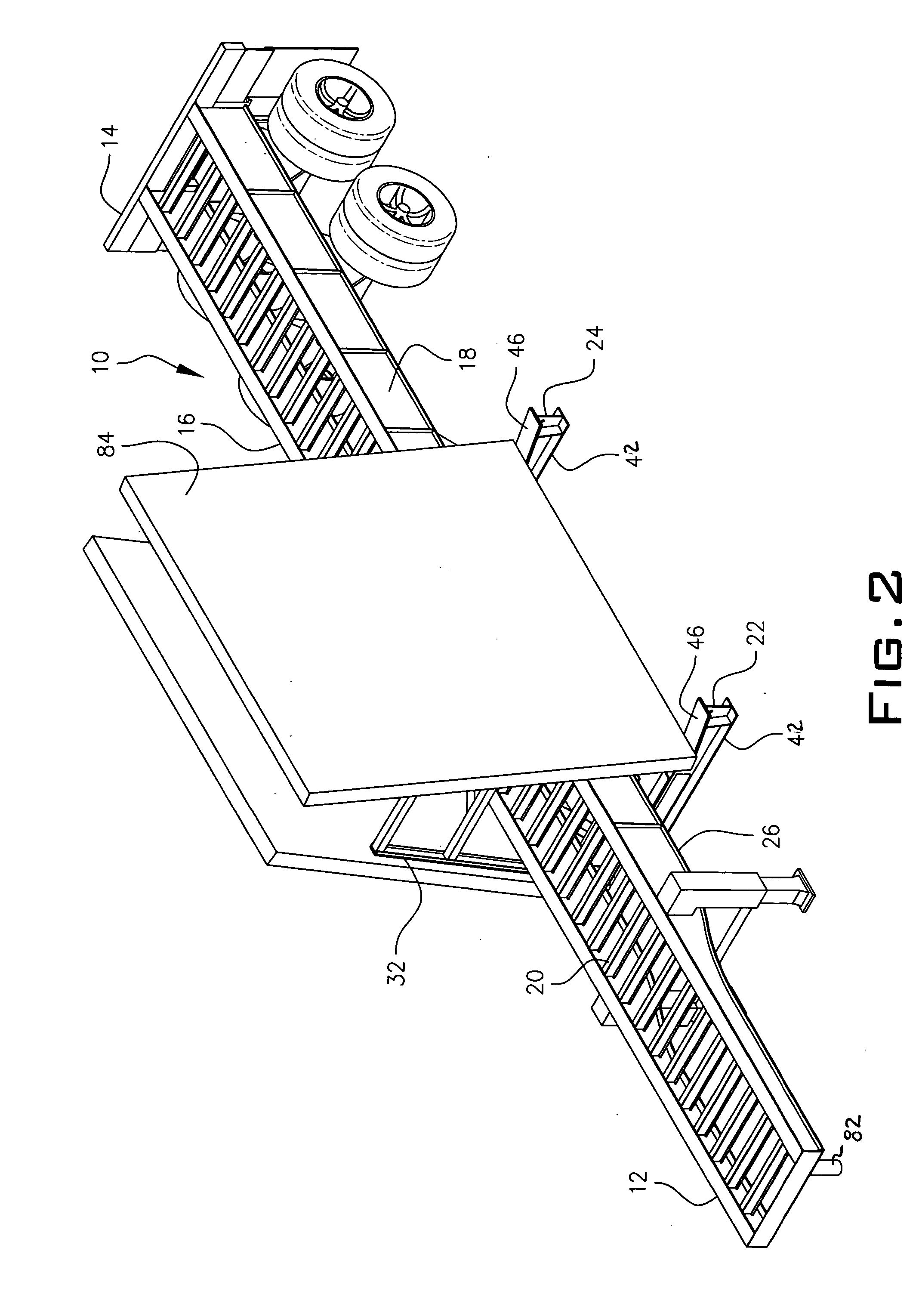
A-frame mounted on a flat bed trailer
a technology for trailers and frames, which is applied in the directions of transportation and packaging, load securing, transportation of items, etc., can solve the problems of not providing a device for easy loading and unloading of building materials
- Summary
- Abstract
- Description
- Claims
- Application Information
AI Technical Summary
Problems solved by technology
Method used
Image

Examples
Embodiment Construction
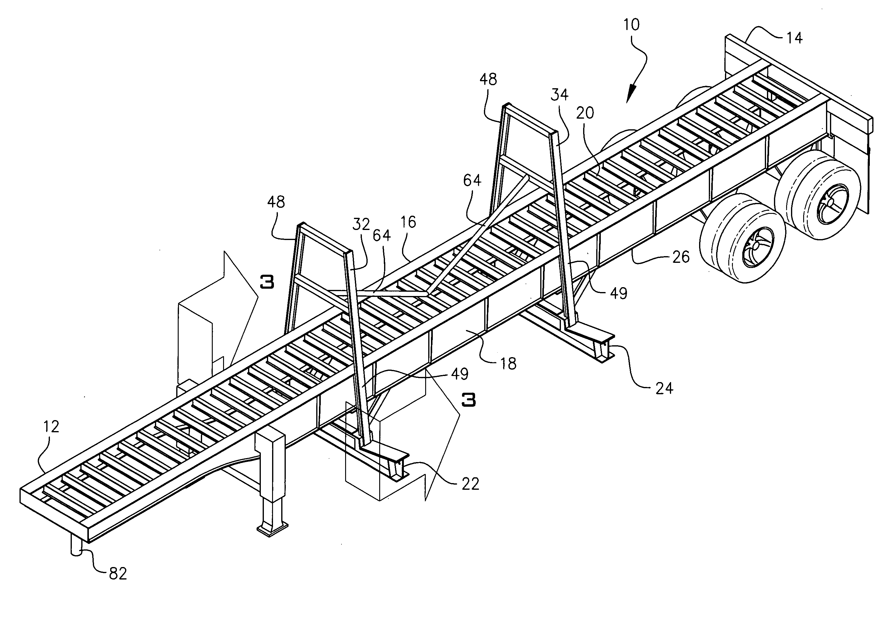
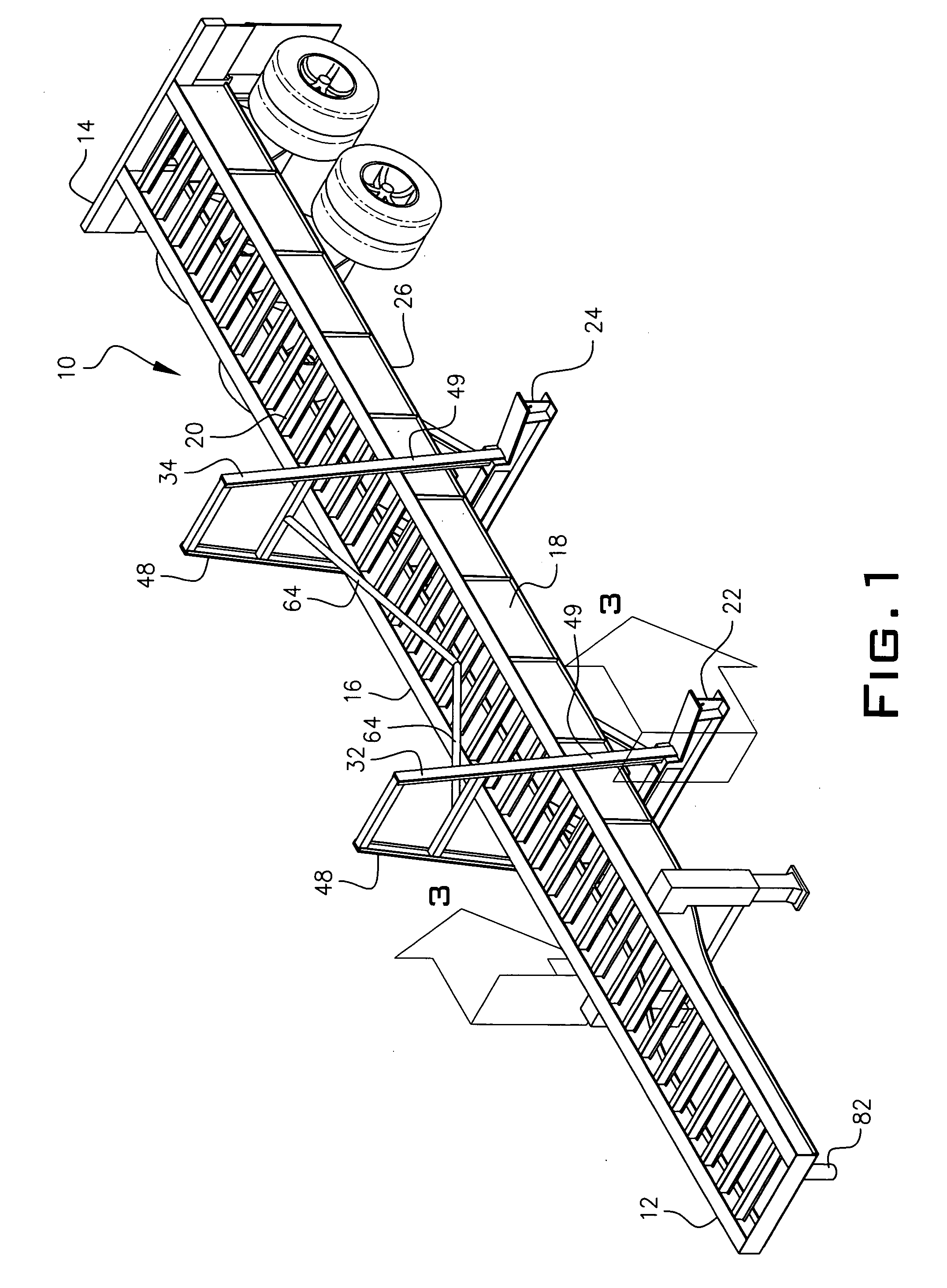
[0012] Throughout the following detailed description, the same reference numerals refer to the same elements in all figures. Referring to FIG. 1, a flat bed trailer 10 has a front portion 12 attachable by standard methods with a wheel pin 82 to a truck cab. The trailer has a rear portion 14 and a right 16 and left 18 side portion. A top surface 20 has a width of about seventy-eight inches. Beams 22 and 24 are axially mounted to the undercarriage 26 of the flat bed trailer 10, usually by welding to the undercarriage. Alternatively, the beams can be bolted to the undercarriage 26. A portion of each beam 22 and 24 extends outwardly and upwardly from the right 16 and left 18 side of the trailer 10.
[0013] Referring to FIG. 3, beam 22 is welded to undercarriage 26. The beam 22 is a two piece construction having a maximum width from end 28 to end 30 of 102 inches. Approximately 24 inches of each end portion of beam 22 projects outwardly and upwardly at an angle of about ten degrees from t...
PUM
 Abstract
Description
Claims
Application Information
 - R&D
- Intellectual Property
- Life Sciences
- Materials
- Tech Scout
- Unparalleled Data Quality
- Higher Quality Content
- 60% Fewer Hallucinations
Browse by: Latest US Patents, China's latest patents, Technical Efficacy Thesaurus, Application Domain, Technology Topic, Popular Technical Reports.
© 2025 PatSnap. All rights reserved.Legal|Privacy policy|Modern Slavery Act Transparency Statement|Sitemap|About US| Contact US: help@patsnap.com