
Acetabular shell impactor

a technology of acetabular shell and impactor, which is applied in the field of surgical instruments, can solve the problems of large incisions, difficulty in correct positioning of acetabular components, and inability of amstutz devices to be used with cementless acetabular shells

Inactive Publication Date: 2005-09-15
PARAMOUNT MEDICAL INSTR
View PDF22 Cites 35 Cited by
  • Summary
  • Abstract
  • Description
  • Claims
  • Application Information

AI Technical Summary

Problems solved by technology

One of the major difficulties confronting the surgeon during hip replacement surgery is the relatively inaccessible location of the acetabulum making it difficult for the surgeon to correctly position the acetabular components.
However, from the patient's perspective, a large incision is undesirable as it increases the trauma to the patient and the recovery time.
The Amstutz device does not appear to be able to be used with cementless acetabular shells that require impaction.
The above devices are characterized by several disadvantages including complicated designs involving several moving parts that both increase manufacturing costs as well as making the device more difficult to use during an operation.
In particular, the Amstutz device disadvantageously requires a connection to an external suction source.
The Amstutz device further does not allow for interchangeable shell-engaging heads to allow the device to be used with different sized acetabular shells.
Finally, it appears that none of the above devices can be used to both implant an acetabular shell and a socket liner.
In addition, the shape of the devices dictate the use of relatively large incisions during surgery.
Unfortunately, despite their advantages, both the Dye and Parker et al. apparatuses still has several shortcomings.
Dye is particularly disadvantageous due to the fact that it does not teach a remote release of the acetabular shell once it is installed in the acetabulum.
Parker et al., on the other hand, is disadvantageous due to its overly complicated remote release mechanism.

Method used


Image

  • Acetabular shell impactor
  • Acetabular shell impactor
  • Acetabular shell impactor

Examples


Embodiment Construction

[0032] For the purposes of promoting an understanding of the principles in accordance with the disclosure, reference will now be made to the embodiments illustrated in the drawings and specific language will be used to describe the same. It will nevertheless be understood that no limitation of the scope of the disclosure is thereby intended. Any alterations and further modifications of the inventive features illustrated herein, and any additional applications of the principles of the disclosure as illustrated herein, which would normally occur to one skilled in the relevant art and having possession of this disclosure, are to be considered within the scope of the disclosure claimed.

[0033] It is also to be understood that the terminology employed herein is used for the purpose of describing particular embodiments only and is not intended to be limiting since the scope of the present disclosure will be limited only by the appended claims and equivalents thereof.

[0034] It must be not...


PUM


Abstract

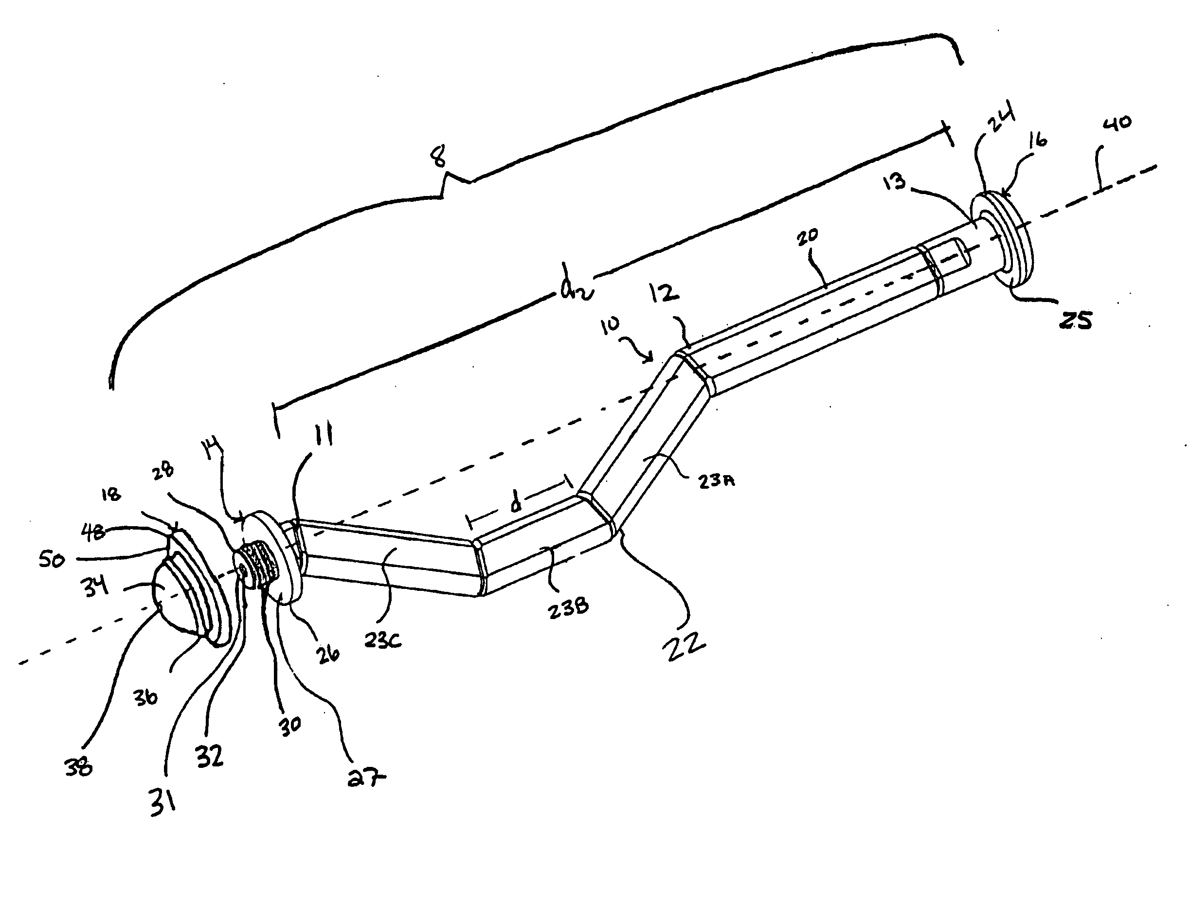
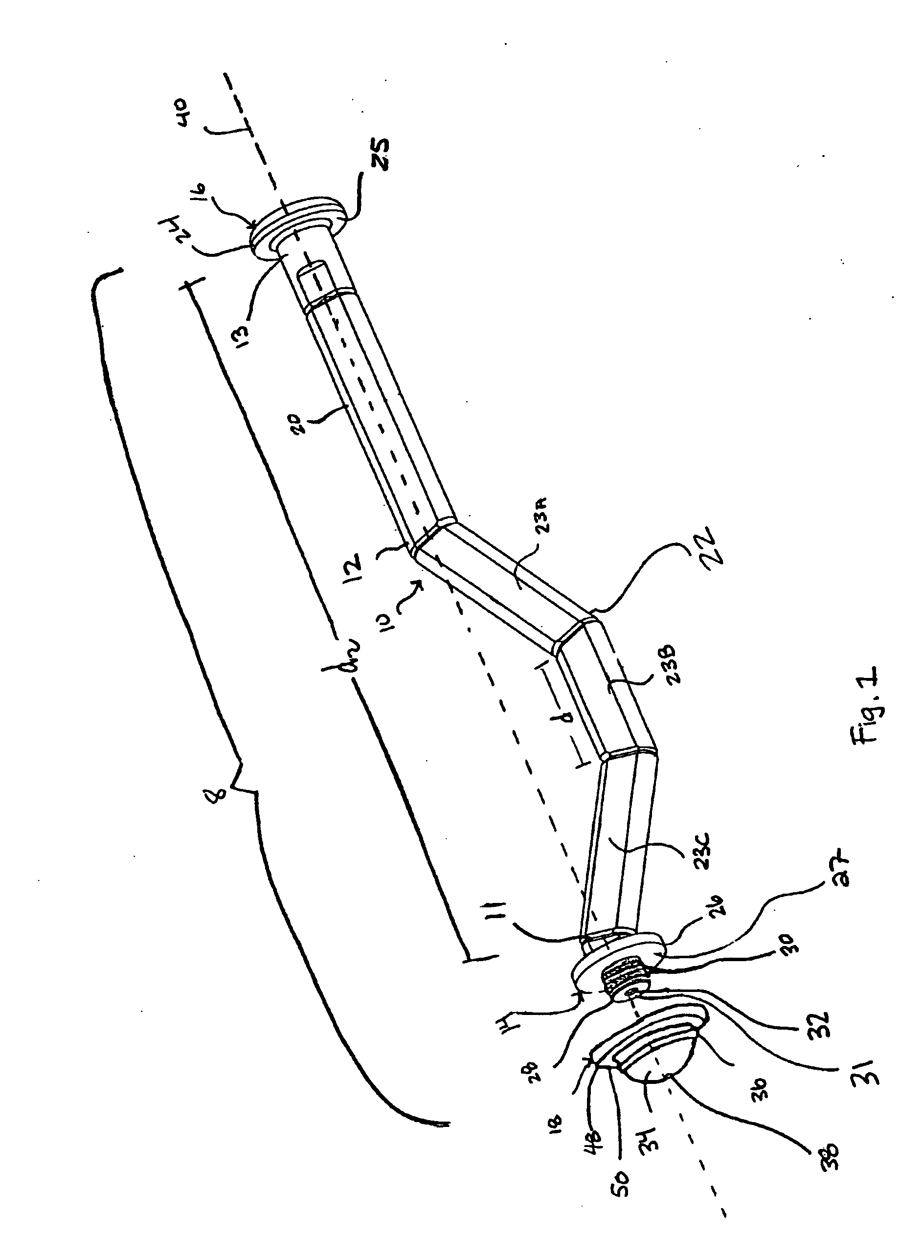
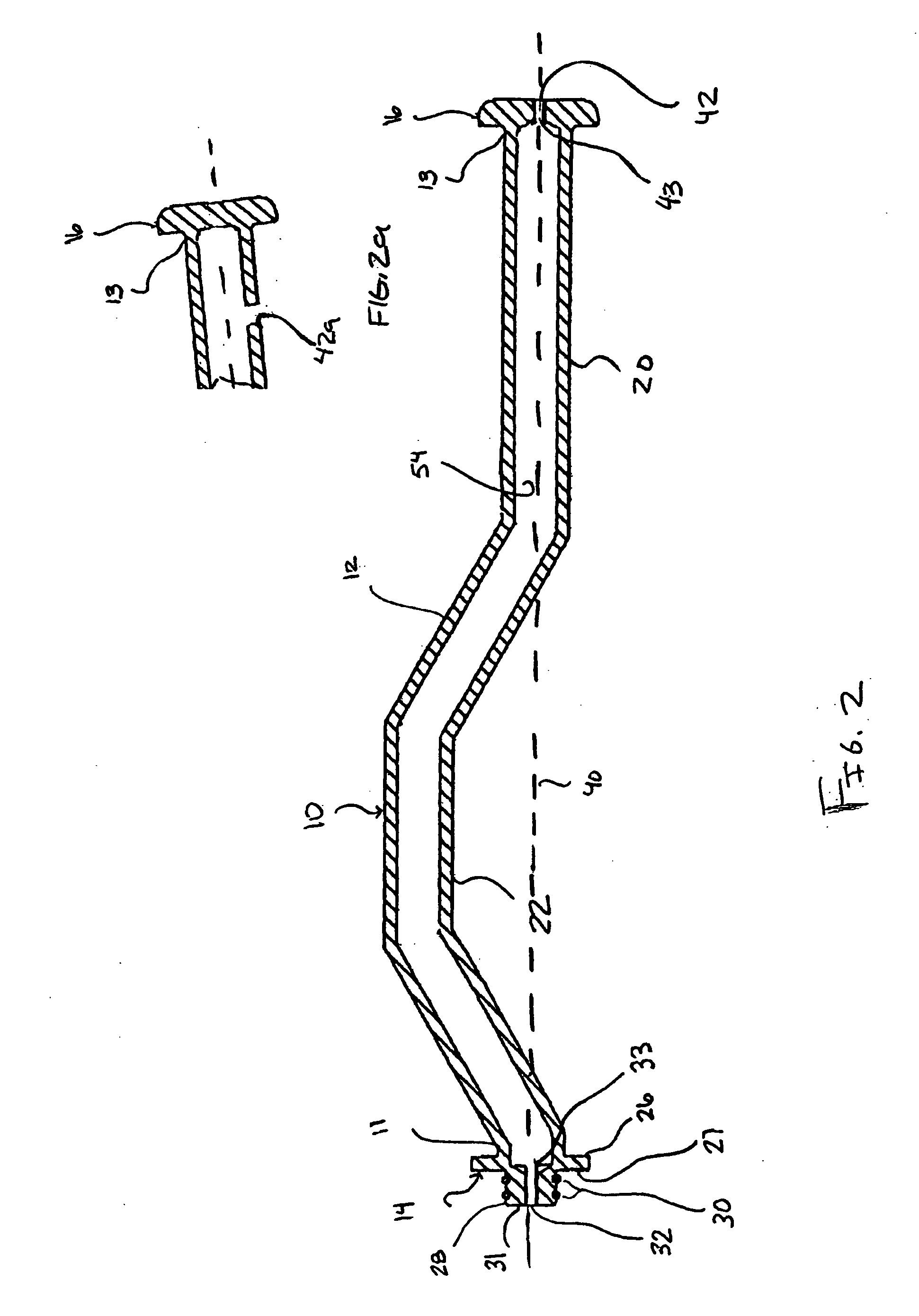
A method and apparatus for implanting acetabular components into an acetabulum utilizing a minimally invasive incision. The method and apparatus utilize a subatmospheric pressure formed in a hollow passage of an elongate body to secure an acetabular shell to a shell-engaging head removably attached to a coupler end of the elongate body. Liner-engaging heads may also be removably attached to the coupler end to install socket liners into an implanted acetabular shell. The elongate body may comprise a bent portion to allow access to the acetabulum through a minimally invasive incision.

Description

CROSS-REFERENCE TO RELATED APPLICATIONS [0001] This application claims the benefit of U.S. Provisional Application No. 60 / 534,431, filed Jan. 5, 2004, and U.S. Provisional Application No. 60 / 541,344, filed Feb. 2, 2004, which applications are hereby incorporated by reference herein in their entireties, including but not limited to those portions that specifically appear hereinafter, the incorporation by reference being made with the following exception: In the event that any portion of the above-referenced provisional applications is inconsistent with this application, this application supercedes said above-referenced provisional applications.STATEMENT REGARDING FEDERALLY SPONSORED RESEARCH OR DEVELOPMENT [0002] Not Applicable. BACKGROUND [0003] 1. The Field of the Invention [0004] The present disclosure relates generally to surgical instruments, and more particularly, but not necessarily entirely, to an apparatus and method for implanting surgical prostheses during surgery. [0005] ...

Claims


Application Information

Patent Timeline
Patent Type & Authority Applications(United States)
IPC IPC(8): A61B17/00A61B17/58A61B17/88A61B17/92A61F2/30A61F2/34A61F2/46
CPCA61B17/00234A61B17/8872A61B17/92A61F2/34A61F2/4609A61F2002/4685A61F2002/4623A61F2002/4624A61F2002/4635A61F2002/4681A61F2002/30616A61F2/4603
Inventor PARRY, DOUGLAS S.PARRY, SCOTT R.
Owner PARAMOUNT MEDICAL INSTR
Learn More