Controller and expansion unit for controller

a controller and expansion unit technology, applied in the field of controllers, can solve the problems of difficulty in meeting new games which require more command buttons, difficult to continuously make commands, and difficult to meet the needs of more command buttons, etc., to facilitate operation, facilitate operation with the fingers, and facilitate operation

Inactive Publication Date: 2005-09-29
SEGA CORP
View PDF14 Cites 115 Cited by
  • Summary
  • Abstract
  • Description
  • Claims
  • Application Information

AI Technical Summary

Benefits of technology

[0025] In the above-described controller expansion unit, the function expansion means may include vibration means for giving a vibration to the controller body, based on the signal from the game apparatus body or the controller body, whereby in a shooting game, for example, vibrations generated upon shooting are added to thereby make the game realistic.
[0043] In the above-described controller it is preferable that a projection is provided on the second operational surface of the controller body; the controller can be placed on a flat surface, supported by the projection and the two grips; the direction key and the command buttons are disposed at positions which facilitate operation with the left and the right thumbs of an operator when the controller is placed on a flat surface, and the command lever is disposed at a position which facilitates with the fingers other than the thumbs. When the controller is placed on a desk or the like to be operated, the controller is set on a flat surface such as a desk or the like, supported by the projection and the two grips, which makes the operation stable.

Problems solved by technology

However, the command buttons of the conventional controller can make only one command by one operation thereof, and is unsuitable to continuously make commands.
It is very difficult especially to make command which are continuously changed.
Six buttons are a limit to be easily operated by one player, which has made it difficult to meet new games which require more command buttons.
Recently the method for operating the controller has become increasingly complicated, which makes it difficult for players to stably operate the controller.
Thus, their functional ability and ease of operation of the controller limit the contents of a game.
Unfortunately, a large burden is places on the users.
Conventional controllers, on the other hand, are totally inconsiderate of a player's grip.
The conventional controller does not meet such requirements.

Method used


Image

  • Controller and expansion unit for controller
  • Controller and expansion unit for controller
  • Controller and expansion unit for controller

Examples


first embodiment

A First Embodiment

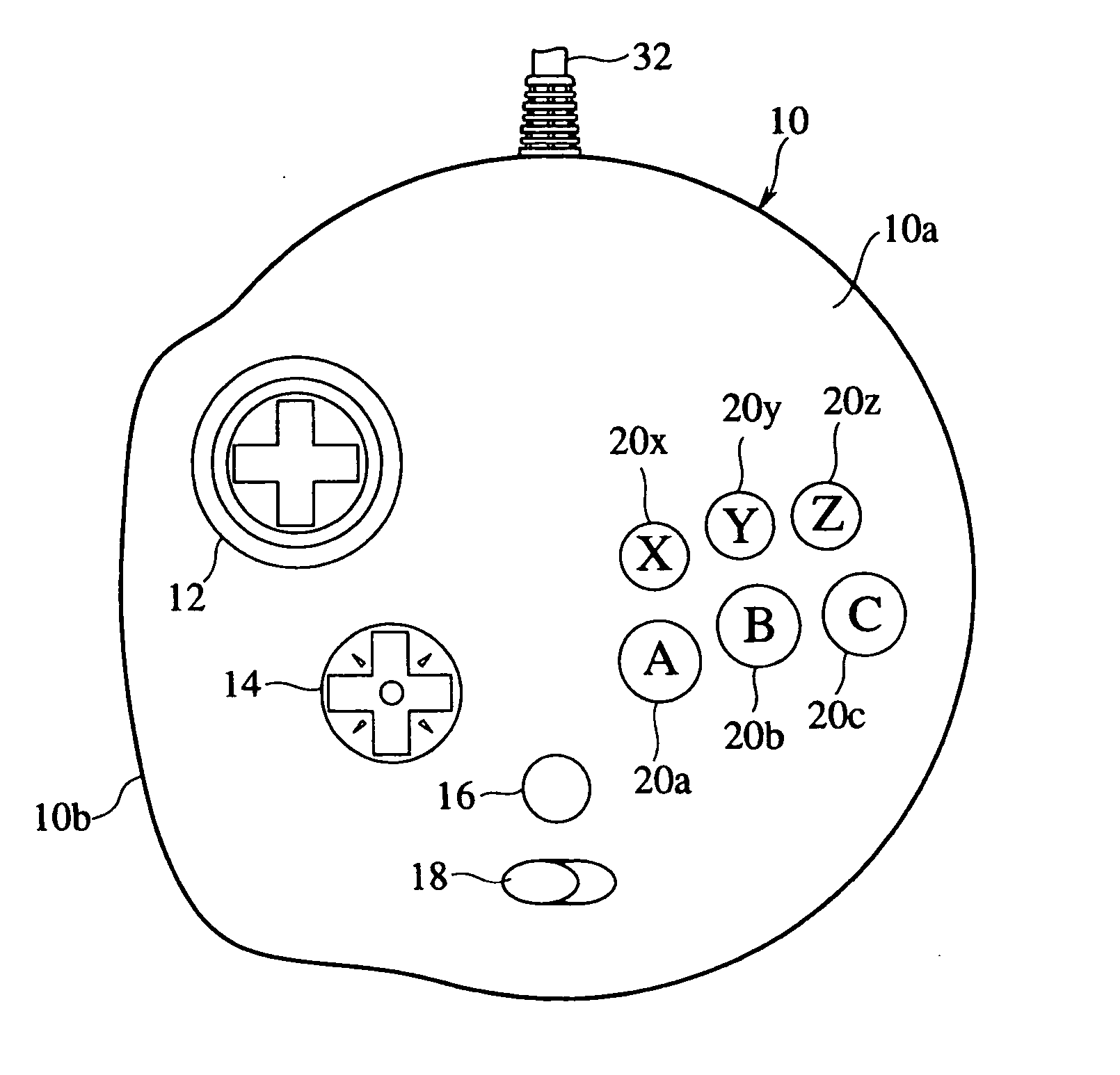
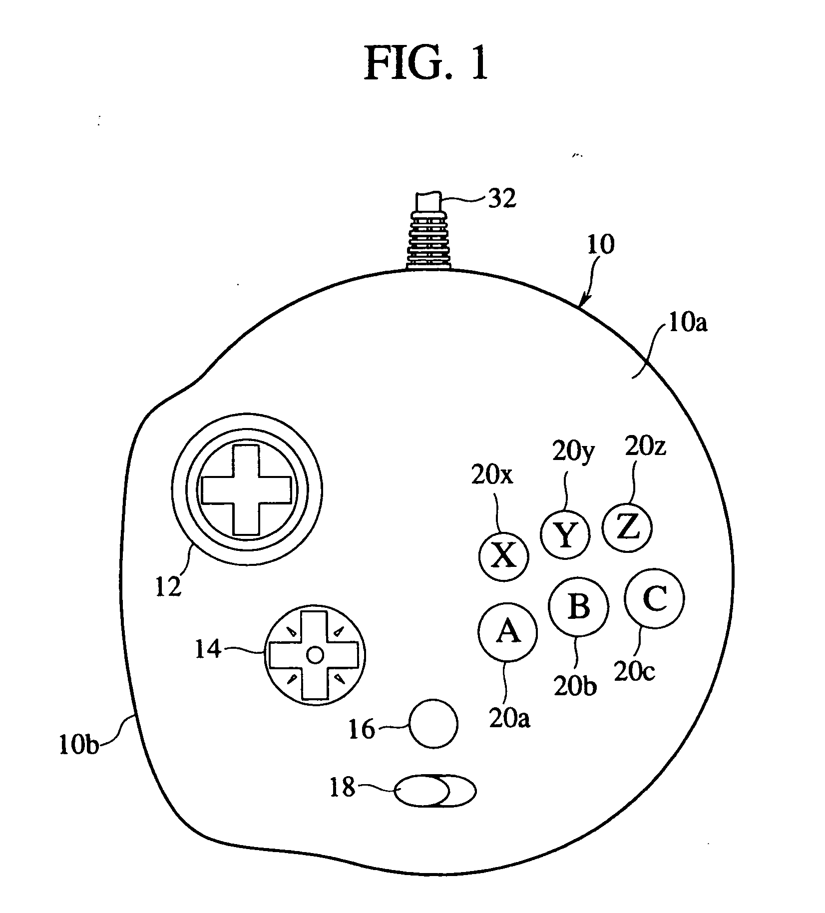
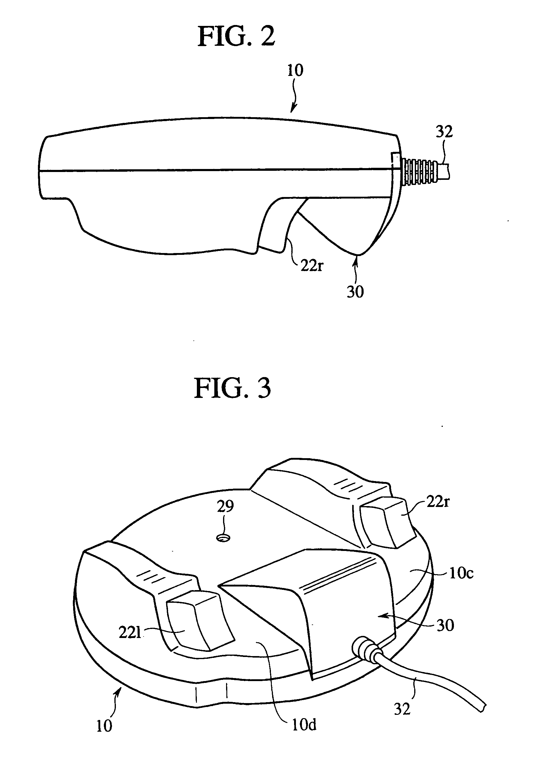
[0094] The controller according to a first embodiment of the present invention will be explained with reference to FIGS. 1 to 34. FIG. 1 is a plan view of the controller according to the present embodiment. FIG. 2 is a right side view of the controller according to the present embodiment. FIG. 3 is a perspective rear side view of the controller according to the present embodiment as slantly viewed. FIG. 4 is a perspective view of the controller according to the present embodiment, which shows a way in which an operator holds the controller. FIG. 5 is a perspective rear side view of the controller according to the present embodiment in a state where the expansion unit are detached from the controller body. FIG. 6 is views of pin arrangements of a connector of the expansion unit and of an expansion socket of the controller body.

[0095] (Structure of the Controller)

[0096] The controller according to the present embodiment comprises a controller body 10 and an expansi...

second embodiment

A Second Embodiment

[0198] The controller according to a second embodiment will be explained with reference to FIGS. 34 to 36. FIG. 35 is plan view of the controller according to the present embodiment. FIG. 36 is a front view of the controller according to the present embodiment. FIG. 37 is a right side view of the controller according to the present embodiment. The same members and members of the same kinds of the present embodiment as those of the first embodiment are represented by the same reference numerals not to repeat or simplify their explanation.

[0199] The controller according to the present embodiment is the same as the first embodiment in that the basic shape of the outside edge of a controller body 10 is circular, and includes two lugs 11l, 11r projected toward a player holding the controller body 10.

[0200] In the first embodiment, the left side of the controller body 10 is formed in a larger-diameter arcuate portion so that when a player grips the controller body 10,...

third embodiment

A Third Embodiment

[0222] The controller according to a third embodiment of the present invention will be explained with reference to FIGS. 48 to 50. FIG. 43 is a plan view of the controller according to the present embodiment. FIG. 45 is a right side view of the controller according to the present embodiment. FIG. 46 is a bottom view of the controller according to the present embodiment.

[0223] As shown in FIG. 43, two grips 512l, 512r for a player to hold with the hands are extended from a controller body 510 toward the player. A connection cable 514 to be connected to a game apparatus body (not shown) is provided at the center of the side opposite to the grips 512l, 512r of the controller body 510.

[0224] A start button 516 is provided at the lower central part of an operational surface 510a which is the upper surface of the controller body 510. A direction key 518 for commanding directions is provided on the left side of the operational surface 510a. Six command buttons 520x, 520...


PUM


Abstract

An expansion unit 50, 60 or 70 is connected to a controller body 10 including an analog direction key 12, a digital direction key 14, command buttons 20a-20z, command levers 22l, 22r, etc. An expansion unit 50 including a photo emitting unit 52 is connected to thereby make the controller cordless. An expansion unit 60 including a photo detecting unit 65, whereby shooting games in which an enemy on a monitor screen can be shot can be played. An expansion unit 70 including a vibration unit 75 is connected, whereby a vibration is given to the controller body 10 to make a shooting game more realistic. New functions can be added to the conventional controller, and the new functions can be added freely without making no change to the controller body.

Description

TECHNICAL FIELD [0001] The present invention relates to a controller which outputs various instructions to an electronic device, such as a game device, by operation of an operator. BACKGROUND ART [0002] More than several years have passed since video game devices for domestic use first appeared, and recently a large variety of entertaining games have been developed. Video games for the domestic use are very popular as an entertainment. Domestic game devices are connected to input means called controllers. Players operate the controllers to output various instructions to the game devices. [0003] Thus the controllers intervene between the players and the game devices, and act as a man-machine interface, and thus are very important to the game devices. The ease of operation as well as the functional ability of the controllers are closely related to the feasibility and entertainment value of games. [0004] Various types of controllers for the domestic game devices have been proposed, but...

Claims


Application Information

Patent Timeline
Patent Type & Authority Applications(United States)
IPC IPC(8): A63F13/24A63F13/20A63F13/23G05G1/00G05G1/02G05G1/04G05G1/08G05G7/02
CPCA63F13/02A63F2300/8076A63F13/06A63F2300/1006A63F2300/1025A63F2300/1031A63F2300/1037A63F2300/1043A63F2300/105A63F2300/1062A63F2300/205A63F2300/206A63F2300/403A63F2300/80A63F2300/8017A63F13/04A63F13/837A63F13/80A63F13/803A63F13/22A63F13/323A63F13/211A63F13/285A63F13/245A63F2300/1018A63F13/24A63F13/23A63F2300/302
Inventor HIMOTO, ATSUNORITOSAKI, KENJI
Owner SEGA CORP
Why Eureka
Try Eureka