Shielded electrical jack connector

a shielded, electrical jack technology, applied in the direction of bridges, bridge structural details, coupling device connections, etc., can solve the problem that the metal from which the tube is drawn cannot be pre-plated

Inactive Publication Date: 2005-10-06
TE CONNECTIVITY CORP
View PDF10 Cites 44 Cited by
  • Summary
  • Abstract
  • Description
  • Claims
  • Application Information

AI Technical Summary

Problems solved by technology

The metal from which the tube is drawn cannot be pre-plated, because the drawing process would damage the plating providing ineffective shielding and grounding qualities.

Method used


Image

  • Shielded electrical jack connector
  • Shielded electrical jack connector
  • Shielded electrical jack connector

Examples


Embodiment Construction

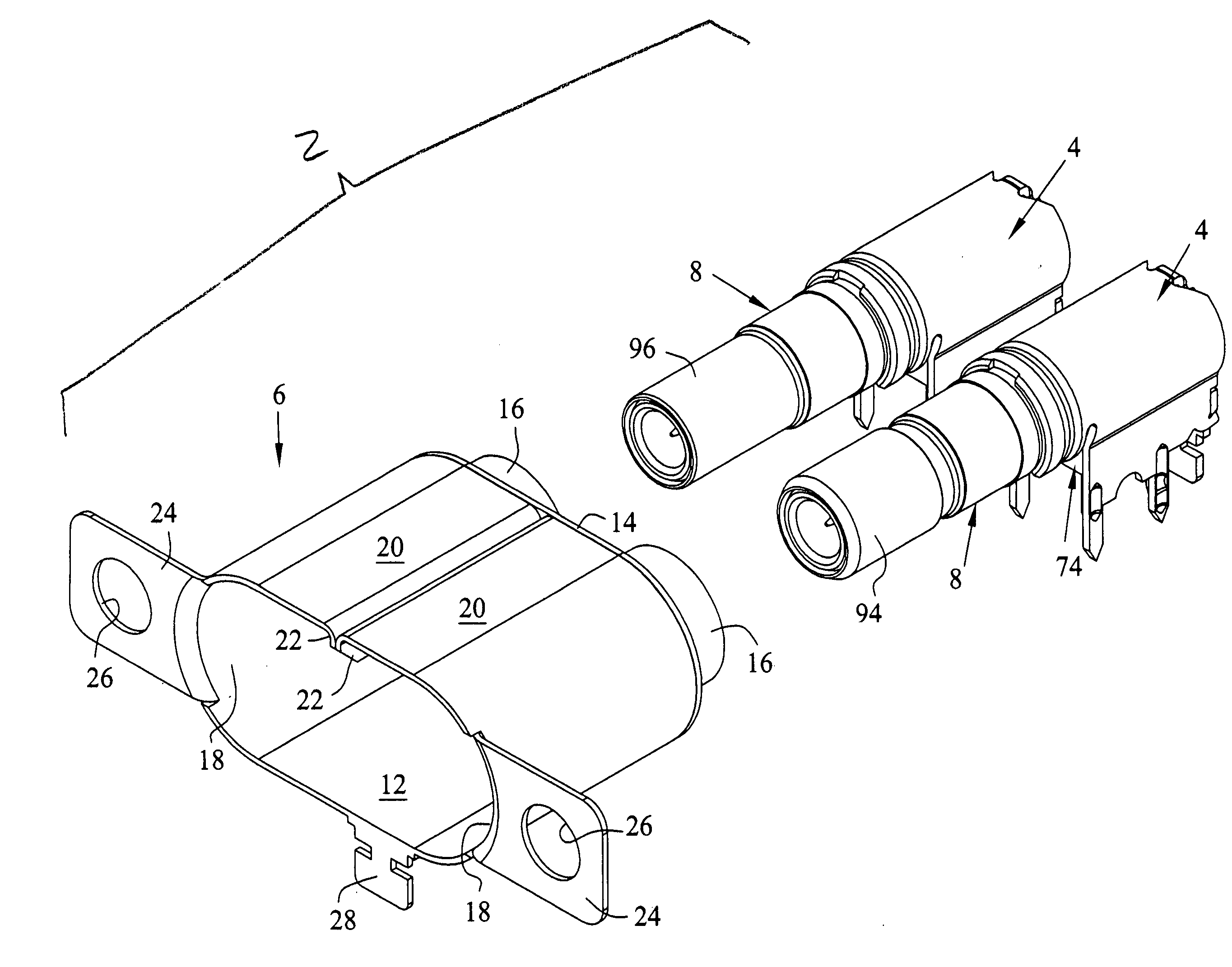
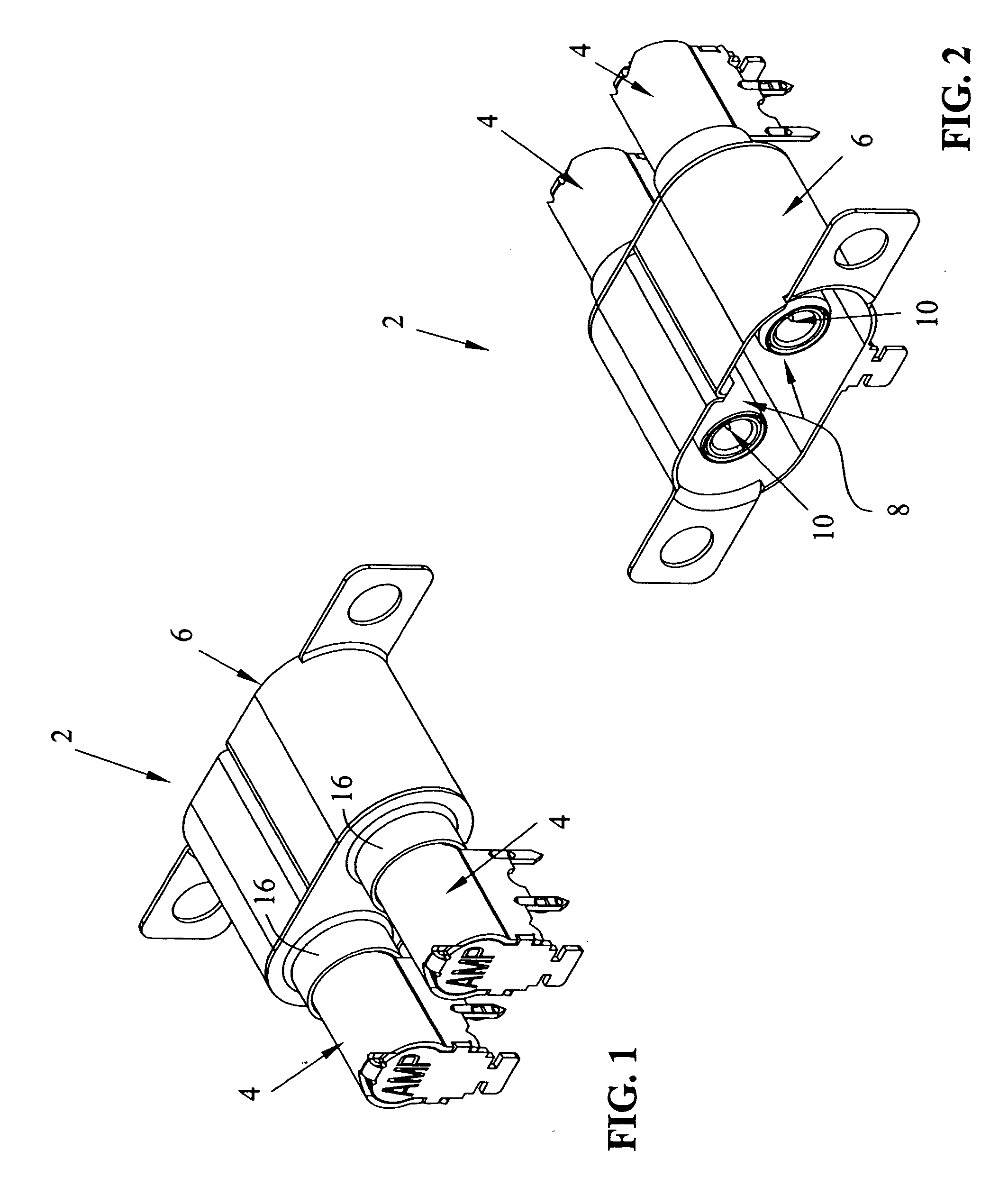
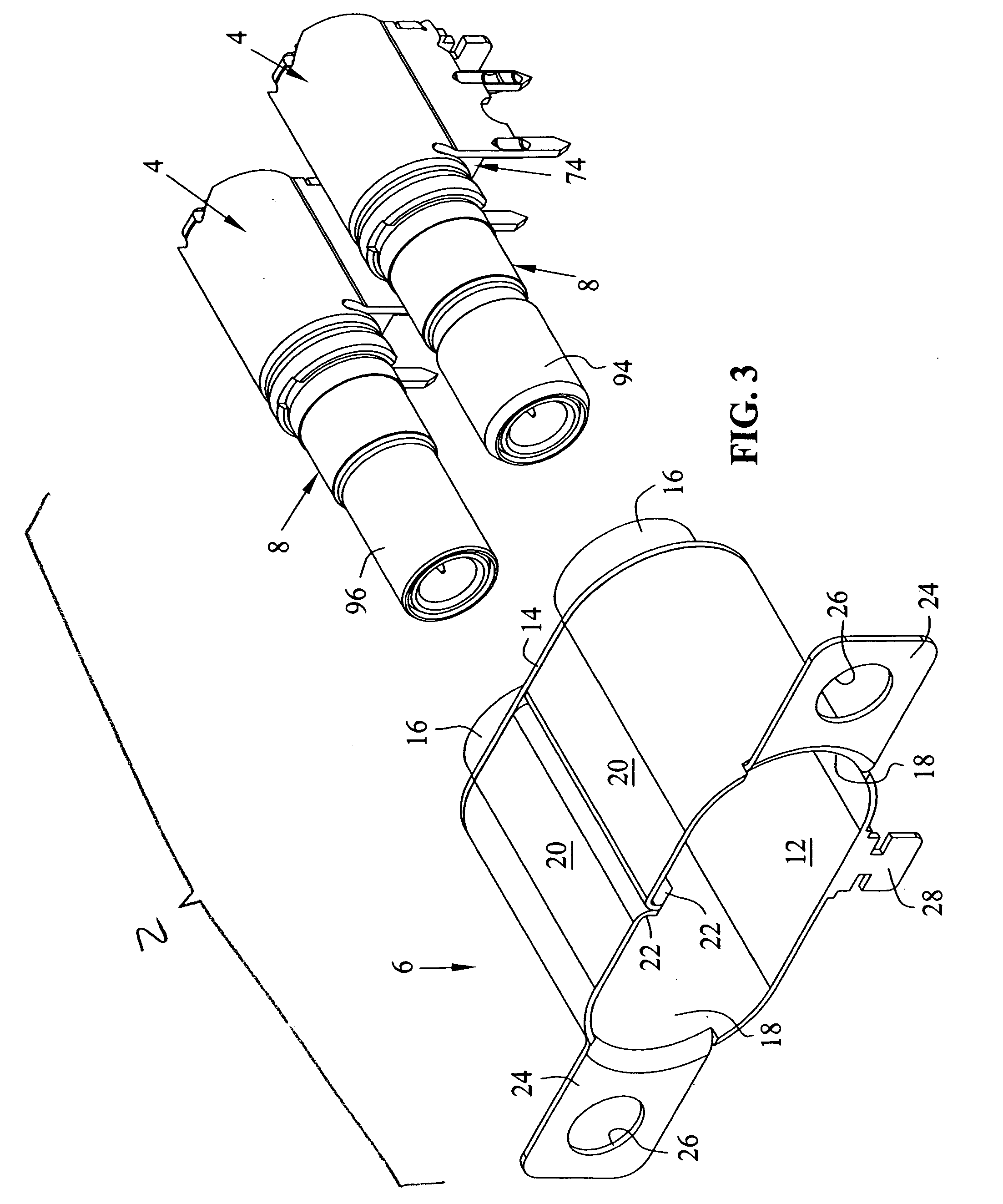
[0024] With respect first to FIGS. 1 and 2, the present invention relates to a jack assembly 2 shown best in FIGS. 1 and 2, which comprises a ground shell member 4, a front shielding shroud 6, cylindrical tubes 8, and pin terminals 10. With reference now to FIG. 3, the outer shroud 6 will be described in greater detail.

[0025] Shroud 6 is stamped and formed from a single sheet of material, where the original sheet is in the plane of lower wall 12. Lower wall 12 is continuous with an end wall 14, which includes drawn openings at 16. Radiused side walls 18 also extend from side edges of lower wall 12 and are reversely bent to form a split upper wall having wall halves 20. Each wall 20 has a seam 22 folded back upon itself so as to form a closed seam. Mounting ears 24 extend from opposite sides of radiused wall sections 18 and include mounting apertures at 26 for mounting to a shielded wall or a bulkhead, as will be described further herein. Finally, a grounding and mounting tab 28 ext...


PUM


Abstract

A shielded jack assembly is shown having a front cylindrical tube, and a rear ground shell portion. The rear ground shell is stamped and formed from pre-plated metal, and includes a partial cylindrical portion, plate portions extending downwardly therefrom, and printed circuit board portions depending from the plate portions. A rear wall portion is integral with the partial cylindrical portion, and depends therefrom via a hinge. The rear wall portion is bent to cover the end opening in the partial cylindrical portion.

Description

BACKGROUND OF THE INVENTION [0001] The subject invention relates to shielded jacks, and more particularly to a stamped and formed jack for mounting on a printed circuit board. [0002] It is common to provide a shielded cable connection to a printed circuit board. Normally these connectors have a pin terminal configured in a right-angle configuration, where a right-angle portion is provided for connection to a printed circuit board. The pin is insulated within a conductive outer shell, where the shell typically comprises a drawn tube of metal, where the drawn tube is plated after the drawing process. The metal from which the tube is drawn cannot be pre-plated, because the drawing process would damage the plating providing ineffective shielding and grounding qualities. The combination of the drawing process and post-plating is an expensive cost adder in the manufacturing process for electrical connectors, and therefore it would be desirable to eliminate this step. [0003] It would be ad...

Claims


Application Information

Patent Timeline
Patent Type & Authority Applications(United States)
IPC IPC(8): H01R12/16H01R12/71H01R13/502H01R13/516H01R13/648H01R13/652H01R13/658H01R13/6581H01R43/00H01R43/18
CPCH01R23/6873H01R24/40H01R43/18H01R2103/00H01R24/50H01R13/6594E01D19/02E01D21/00
Inventor MYER, JOHN M.HARDY, DOUGLAS J.COBLE, KELLIE
Owner TE CONNECTIVITY CORP
Why Eureka
Try Eureka