Spinal cross-connectors

Inactive Publication Date: 2005-10-13
DEPUY SPINE INC (US)
View PDF99 Cites 261 Cited by
  • Summary
  • Abstract
  • Description
  • Claims
  • Application Information

AI Technical Summary

Benefits of technology

[0006] The present invention provides an implantable spinal cross-connector for connecting spinal fixation devices, and more preferably for connecting two spinal fixation rods to one another. In one embodiment, the cross-connector includes a central portion having at least one connector member formed on a terminal end thereof and having first and second opposed jaws, at least one of which is selectively movable between a first, open position wherein the first and second jaws are posi

Problems solved by technology

While current spinal cross-connectors have proven effective, difficulties have been encountered in mounting the cross-connectors, and maintaining them in a desired position and orientation with respect to the spinal rod, or other spinal fixation device to which they are attached.
In particular, the cl

Method used


Image

  • Spinal cross-connectors
  • Spinal cross-connectors
  • Spinal cross-connectors

Examples


Embodiment Construction

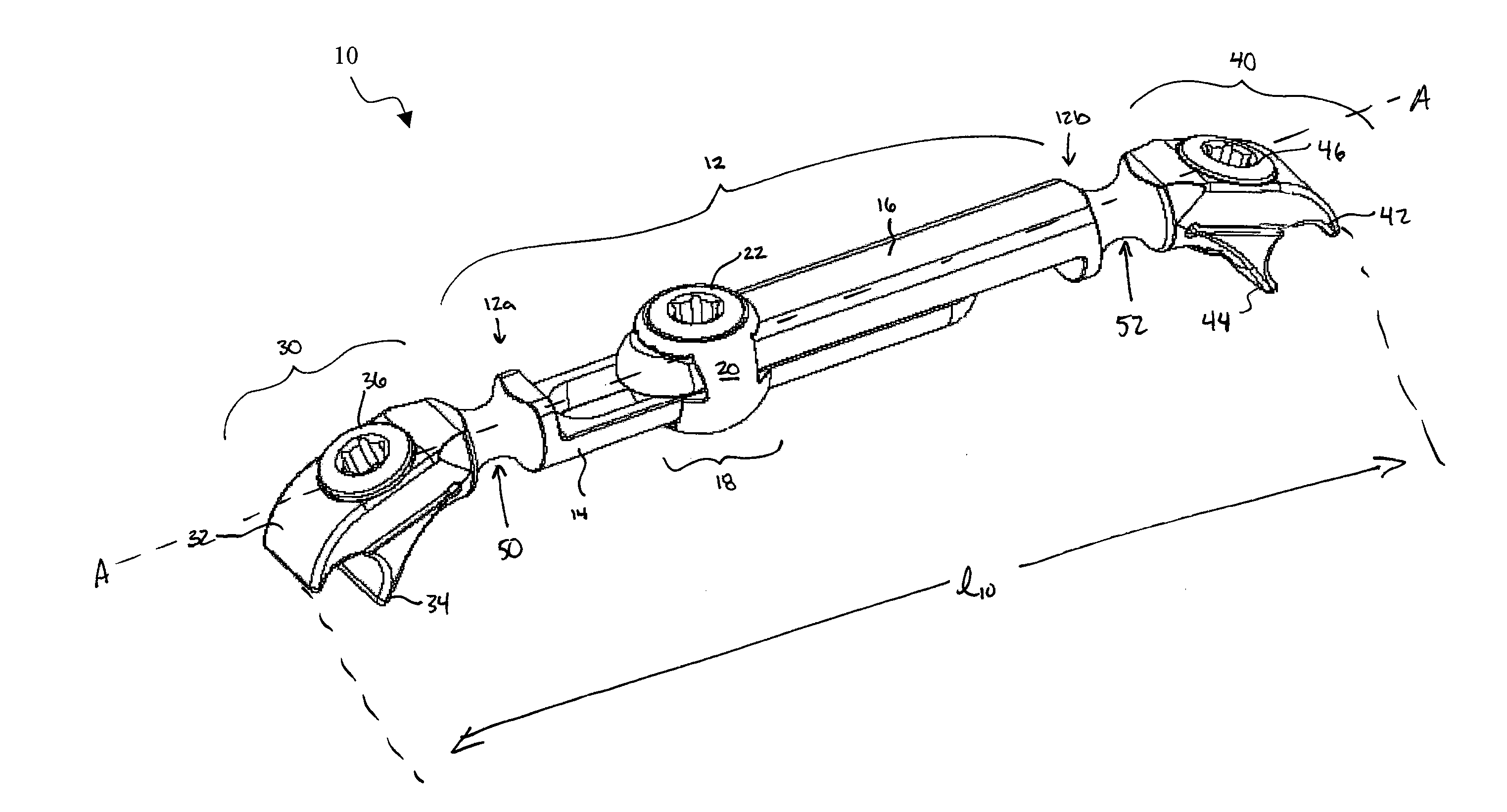
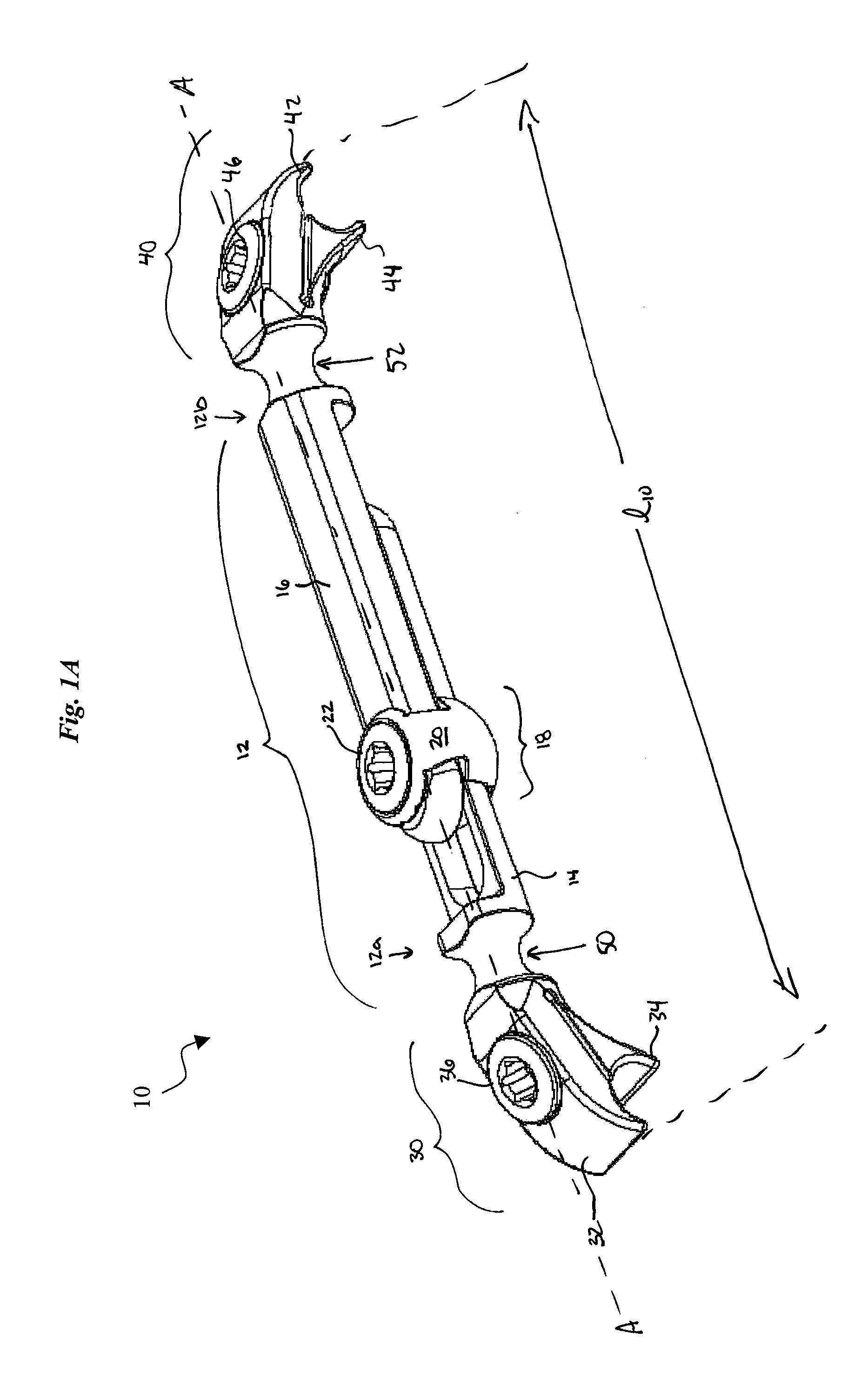
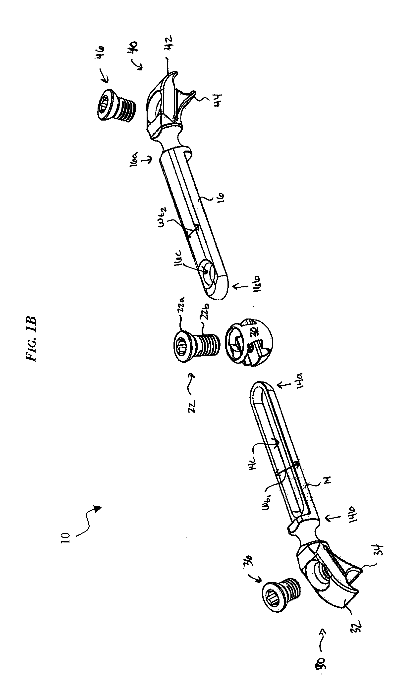
[0028] The present invention provides a spinal cross-connector for connecting one or more spinal fixation devices, and more preferably for connecting two spinal fixation rods that are implanted within a patient's spinal system. FIGS. 1A-9 illustrate various embodiments of exemplary cross-connectors 10, 100, 200, 300, 400 in accordance with the present invention, and in each of the illustrated embodiments the cross-connector 10, 100, 200, 300, 400 generally includes a central portion 12, 112, 212, 312, 412 having at least one connector member, e.g., connector members 30, 40, 130, 140, 230, 240, 330, 340, 430, 440 formed on a terminal end thereof. Each connector member 30, 40, 130, 140, 230, 240, 330, 340, 430, 440 can have a variety of configurations. In the embodiments illustrated in FIGS. 1A-7, the connector members 30, 40, 130, 140, 230, 240 each have first and second opposed jaws 32, 34, 42, 44, 132, 134, 142, 144, 232, 234, 242, 244, at least one of which is selectively movable ...


PUM


Abstract

An implantable spinal cross-connector is provided for connecting one or more spinal fixation devices, and more preferably for connecting two spinal fixation rods that are implanted within a patient's spinal system. In general, the cross-connector includes a central portion having at least one connector member formed on a terminal end thereof and having first and second opposed jaws, at least one of which is selectively movable between a first, open position wherein the first and second jaws are positioned a distance apart from one another, and a second, closed position, wherein the first and second jaws are adapted to engage a spinal fixation element therebetween. The cross-connector also includes a locking mechanism having a shank that is receivable within a non-expandable bore formed in the connector member. The locking mechanism is adapted to come into contact with each of the first and second jaws to selectively lock the first and second jaws in a fixed position with respect to one another.

Description

FIELD OF THE INVENTION [0001] The present invention relates to spinal fixation devices, and in particular to a cross-connector for connecting spinal fixation devices, such as spinal fixation rods implanted in a patient's spinal system. BACKGROUND OF THE INVENTION [0002] Spinal fixation devices are used in orthopedic surgery to align and / or fix a desired relationship between adjacent vertebral bodies. Such devices typically include a spinal fixation element, such as a relatively rigid fixation rod, that is coupled to adjacent vertebrae by attaching the element to various anchoring devices, such as hooks, bolts, wires, or screws. Often two rods are disposed on opposite sides of the spinous process in a substantially parallel relationship. The fixation rods can have a predetermined contour that has been designed according to the properties of the target implantation site, and once installed, the rods hold the vertebrae in a desired spatial relationship, either until desired healing or ...

Claims


Application Information

Patent Timeline
IPC IPC(8): A61B17/58A61B17/70
CPCA61B17/7052
Inventor CHAO, NAM T.RYBICKI, CHRISJONES, BRYAN S.
Owner DEPUY SPINE INC (US)
Why Eureka
Try Eureka