Curved saw

Inactive Publication Date: 2005-10-20
KANZAWA SEIKO
View PDF9 Cites 34 Cited by
  • Summary
  • Abstract
  • Description
  • Claims
  • Application Information

AI Technical Summary

Benefits of technology

[0010] In light of the foregoing, it is an object of the present invention to provide a

Problems solved by technology

At this time, a pruning saw having saw teeth arranged on a straight line requires a large effort to cut the material because the front end of the blade has to be pressed hard against the material.
This is inconvenient when pruning out-of-reach branches using a saw blade attached to the front end of a long handle, because it is difficult to press the saw blade hard against the material.
As a result,

Method used


Image

  • Curved saw
  • Curved saw
  • Curved saw

Examples


Example

[0021] Preferred embodiments of the curved saw according to the present invention will now be described with reference to the accompanying drawings.

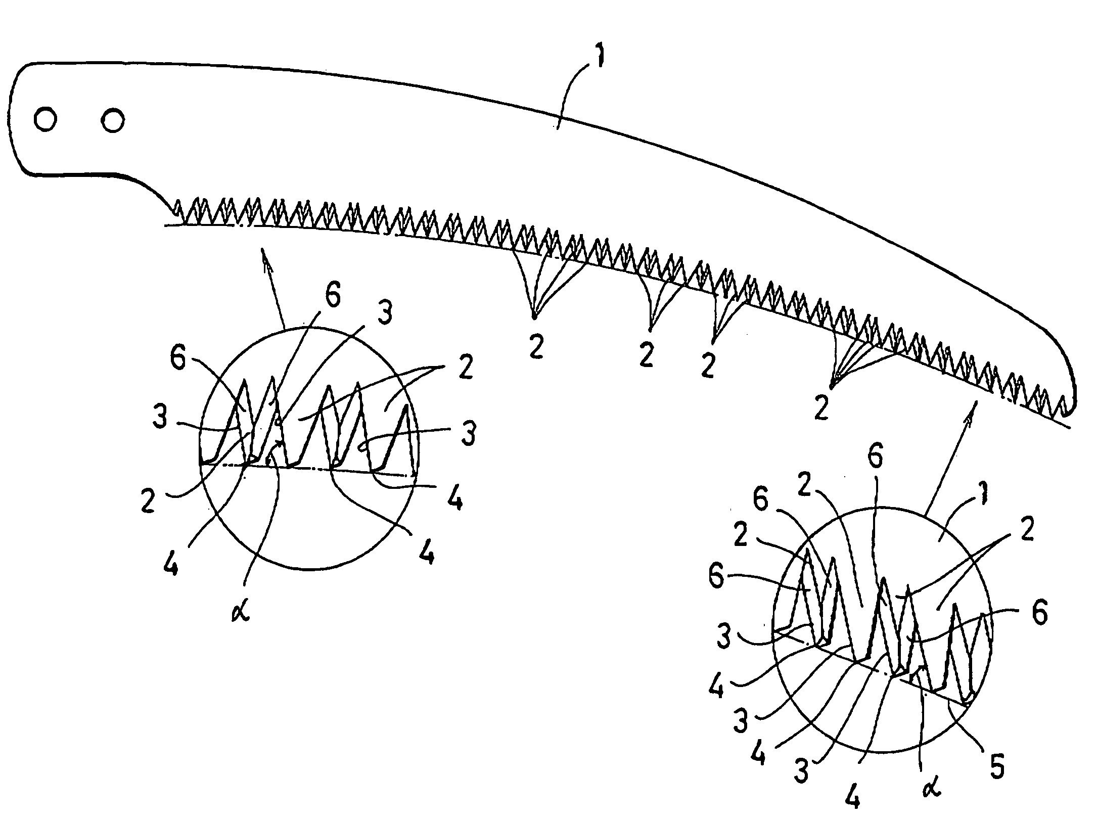
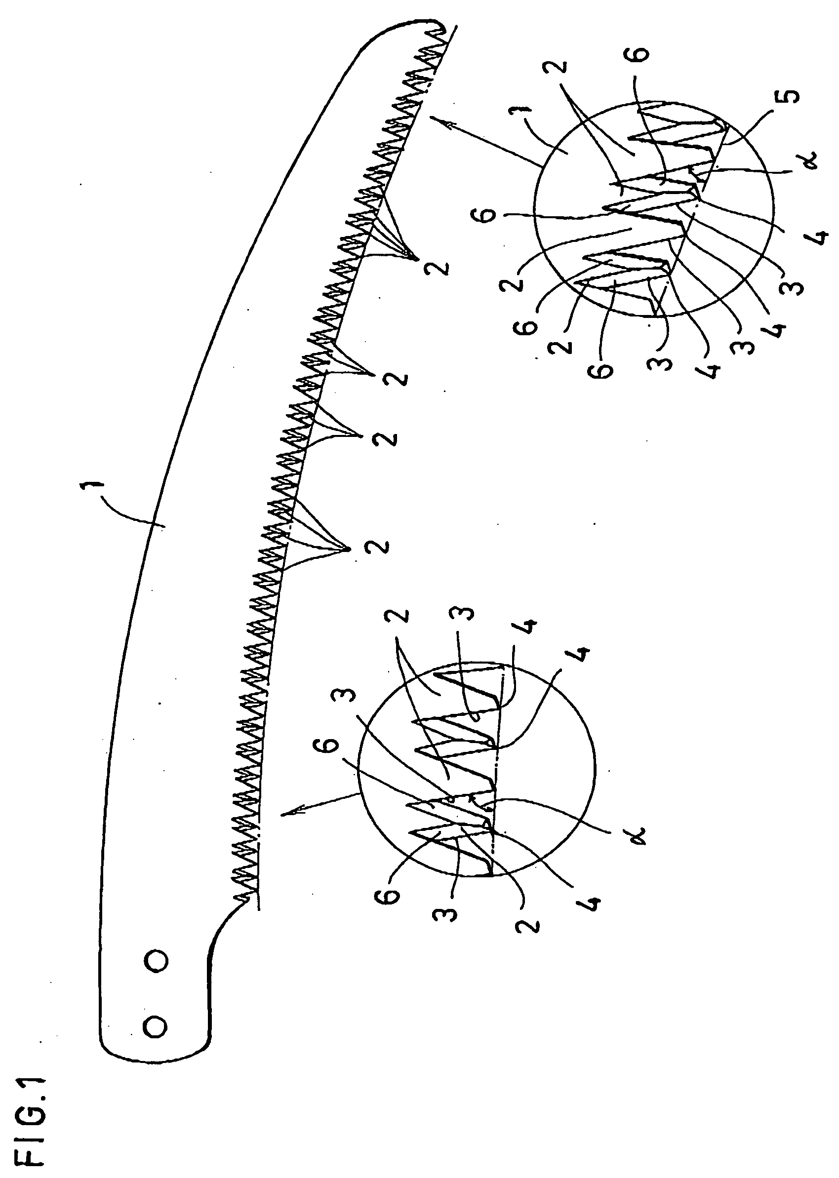
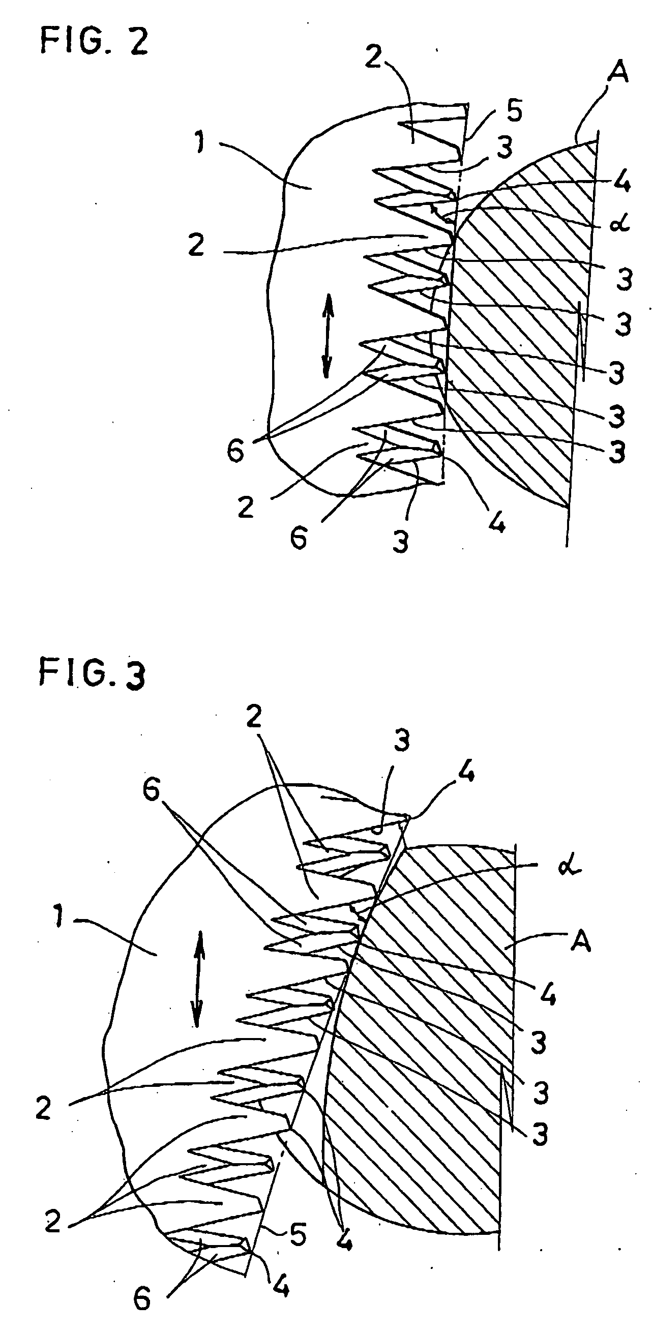
[0022]FIG. 1 shows the entire body of the saw blade of the curved saw according to the present invention. FIG. 2 shows the section of a material being cut by the back end of the saw blade of the present invention. FIG. 3 shows the section of a material being cut by the front end of the saw blade.

[0023] The saw blade 1 of the curved saw shown in FIG. 1 is a pruning saw used mainly for pruning standing trees and fruit trees.

[0024] The saw blade 1, which curves from the back end to the front end, has a multitude of saw teeth 2 formed on its curved and concave edge. The saw teeth 2 are shaped basically the same as conventional saw teeth 2, but the present invention is characterized by the directions in which these saw teeth extend.

[0025] More specifically, each of the saw teeth 2 is formed in a triangular shape on the curved and concave ...


PUM

PropertyMeasurementUnit
Angleaaaaaaaaaa

Abstract

A curved saw having a saw blade 1 curved from the back end to the front end. A multitude of saw teeth 2 are formed on the concave edge of the curved saw blade 1 in such a way that angles α of tooth flanks 3 near the back end of the saw blade 1 with respect to the edge line 5, which connects the tooth tips 4 of the saw teeth, are relatively larger than angles α of tooth flanks 3 near the front end of the saw blade 1 with respect to the edge line 5.

Description

BACKGROUND OF THE INVENTION [0001] 1. Field of the Invention [0002] The present invention relates to a curved saw and more particularly to shapes of teeth of a curved saw with a curved blade having a multitude of saw teeth formed on its concave edge. [0003] 2. Prior Art [0004] When pruning a standing tree or a fruit tree using a pruning saw, the saw teeth have to be pressed against the material to be cut for effective pruning. At this time, a pruning saw having saw teeth arranged on a straight line requires a large effort to cut the material because the front end of the blade has to be pressed hard against the material. As a result, people tend to cut the material using only the back end of the blade. This is inconvenient when pruning out-of-reach branches using a saw blade attached to the front end of a long handle, because it is difficult to press the saw blade hard against the material. As a means for solving this problem, a curved saw having a curved blade and a multitude of saw...

Claims


Application Information

Patent Timeline
IPC IPC(8): A01G23/00A01G3/08B23D61/12B26B9/02B27B21/00B27B21/02B27B21/04
CPCB23D61/12B23D61/123B23D61/121A01G3/08B27B21/00B27B21/04F16K15/20B63B7/00B63B2231/44
Inventor KANZAWA, KUNIYUKI
Owner KANZAWA SEIKO
Why Eureka
Try Eureka