Anti-sweat heater control system and method

a control system and heater technology, applied in the direction of defrosting, cooling fluid circulation, domestic applications, etc., can solve the problems of large amount of “anti-sweat” required, the heat put into the frame is roughly half of the heat, and the electricity cost is significant, so as to achieve the effect of reducing condensation and/or eliminating condensation

a control system and heater technology, applied in the direction of defrosting, cooling fluid circulation, domestic applications, etc., can solve the problems of large amount of “anti-sweat” required, the heat put into the frame is roughly half of the heat, and the electricity cost is significant, so as to achieve the effect of reducing condensation and/or eliminating condensation

US20050229614A1Inactive Publication Date: 2005-10-20ALTECH CONTROLS

Image

  • Anti-sweat heater control system and method
  • Anti-sweat heater control system and method
  • Anti-sweat heater control system and method

Examples


Embodiment Construction

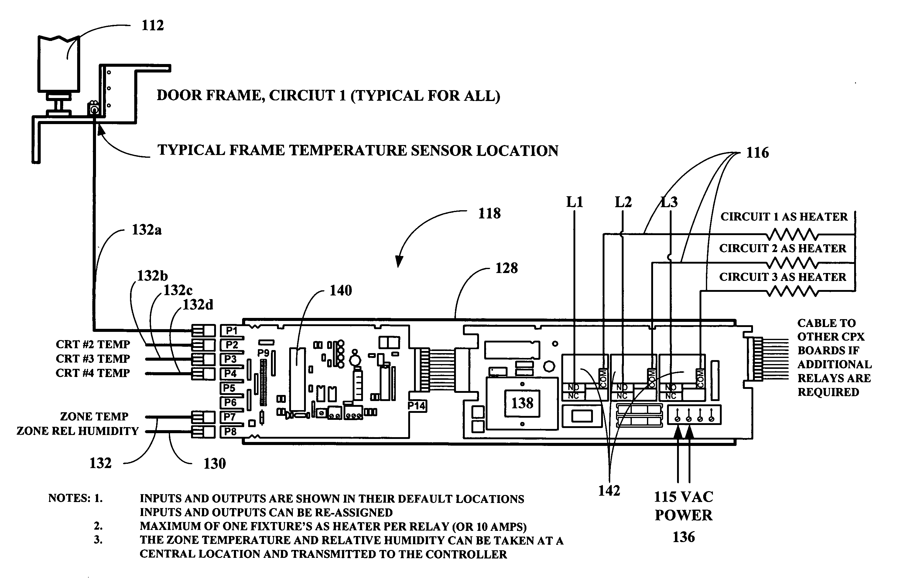
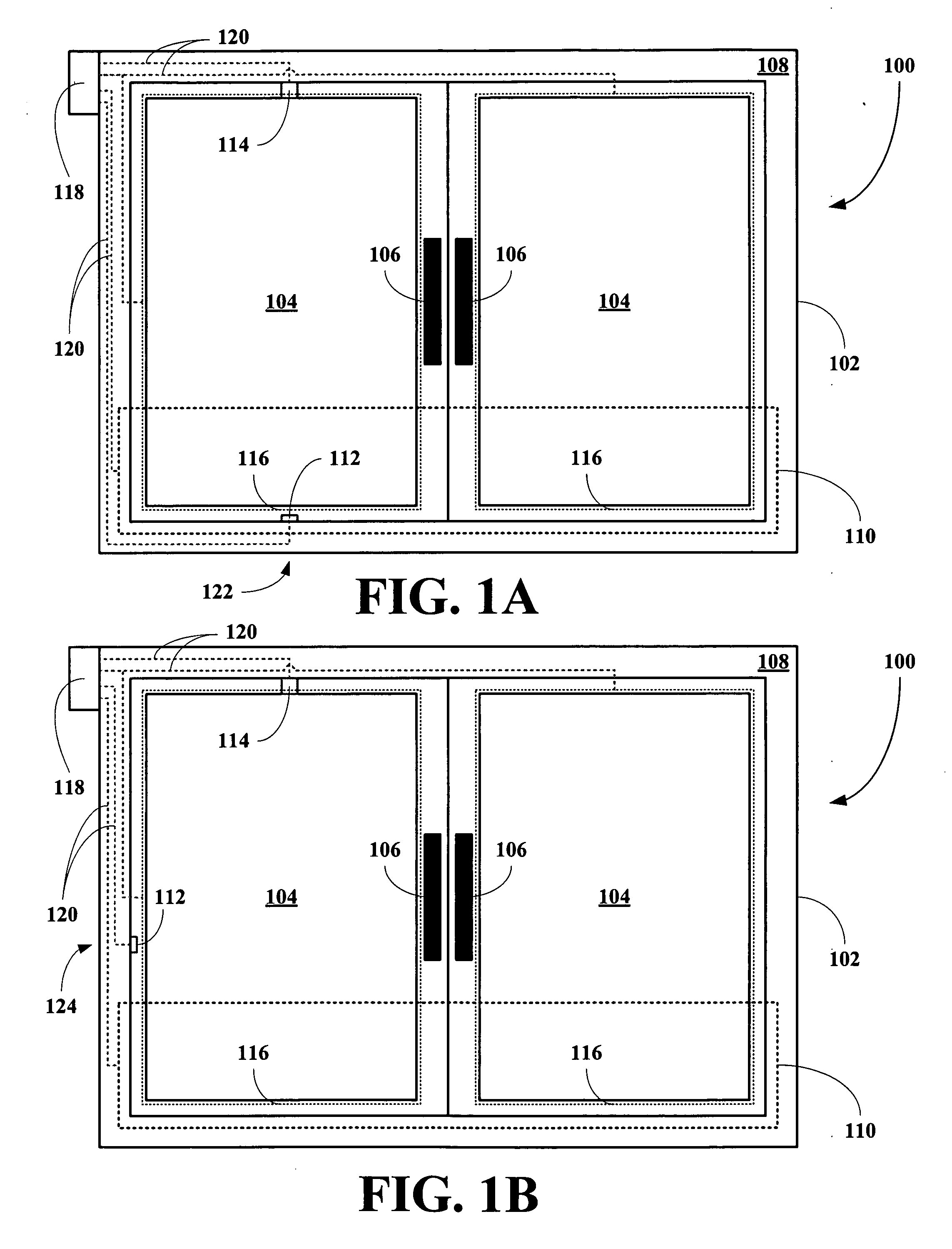
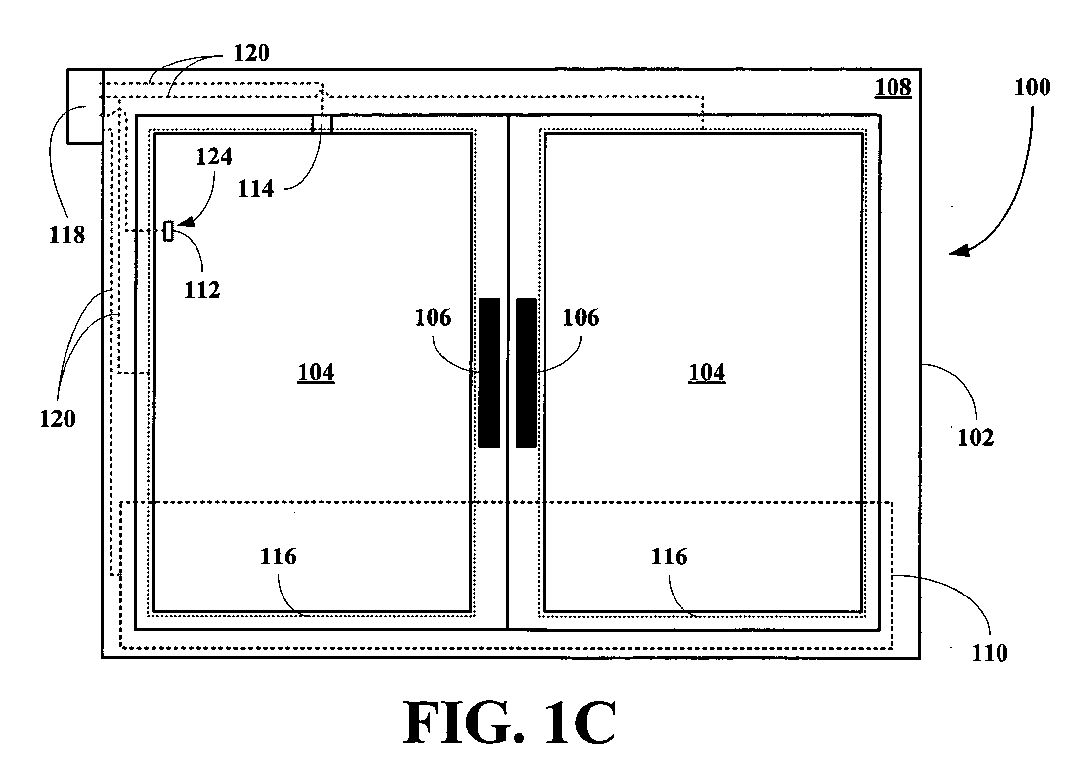
[0018] The inventors have found that an anti-sweat heater control system can be incorporated into a refrigeration circuit of a refrigerated container or plurality of refrigerated containers, where the control system includes a plurality of heaters, one for each door frame or outer surface for which anti-sweat protection is desired, a temperature sensor located at a location on or associated with at least one door frame or outer surface of the refrigerated container and a zone relative humidity sensor, where the heaters are turned on whenever the temperature sensor reading is below a diversity factor corrected set point temperature and where the diversity factor is a difference between the temperature sensor reading and a critical temperature. The benefits of using a “diversity” factor verses a fixed set point are that: (1) the temperature sensor can be located where it is convenient rather than having to locate the sensor at the critical location, which may not be in a particularly ...


PUM


Abstract

An improved anti-sweat heater control system is disclosed for reducing and / or eliminating sweat on cooled surfaces of a refrigerated container. A method for reducing or eliminating sweat from forming on cooled surfaces of a refrigerated container is also disclosed. A refrigerated container incorporating the anti-sweat heater control is also disclosed.

Description

RELATED APPLICATIONS [0001] This application claims provisional priority to U.S. Provisional Patent Application Ser. No. 60 / 559,113, filed 2 Apr. 2004.BACKGROUND OF THE INVENTION [0002] 1. Field of the Invention [0003] The present invention relates to a system and method for heating outer surfaces of a cooled container to prevent condensation or sweat. [0004] More particularly, the present invention relates to a system and method for heating outer surfaces of a cooled container to prevent condensation or sweat, where the apparatus includes a container, a cooling system and a heating system, where the heating system maintains the outer surfaces above a dew point temperature of a lowest temperature point on the outer surfaces for which anti-sweat protection is desired. [0005] 2. Description of the Related Art [0006] Many refrigerated display cases require electric strip heaters to be installed in the materials near the interface between the refrigerated zone and the ambient zone to pr...

Claims


Application Information

Patent Timeline
20 Oct 2005
Publication
US20050229614A1
IPC
A47F3/04; F25D21/00; F25D21/04; F25D29/00
CPC
A47F3/0482; F25B2700/02; F25D2700/14; F25D29/00; F25D2500/04; F25D21/04
Inventors
ANSTED, ROGER