Heated seal air for valve and regenerative thermal oxidizer containing same

a technology of regenerative thermal oxidizer and valve seal, which is applied in the direction of lighting and heating apparatus, combustion types, furnaces, etc., can solve the problems of valve wear, disturbance and fluctuation of pressure and/or flow in the system, and reduce the efficiency of the apparatus, so as to reduce or eliminate the condensation of substances, the effect of cost-effectiveness

Active Publication Date: 2005-06-02
DURR SYST INC
View PDF34 Cites 0 Cited by
  • Summary
  • Abstract
  • Description
  • Claims
  • Application Information

AI Technical Summary

Benefits of technology

[0007] The problems of the prior art have been overcome by the present invention, which provides a gas seal for a switching valve, and a regenerative thermal oxidizer including the switching valve. The seal of the present invention utilizes gas, preferably air, that is at a sufficiently high temperature to minimize or eliminate condensation of substances that would otherwise condense as a result of being cooled by the sealing gas. In a preferred embodiment, the sealing gas is heated by heat exchange with exhaust air from the regenerative thermal oxidizer, thereby providing a cost-effective solution to deleterious condensation.
[0008] Strategic location of the heat exchanger for heating the sealing gas allows for compact construction and simplicity in retrofitting the heat exchanger into existing units.

Problems solved by technology

Any leakage of untreated process gas through the valve system will decrease the efficiency of the apparatus.
In addition, disturbances and fluctuations in the pressure and / or flow in the system can be caused during valve switchover and are undesirable.
Valve wear is also problematic, especially in view of the high frequency of valve switching in regenerative thermal oxidizer applications.
In systems using positive pressure gas, the cooling effect of this seal air can cause deposits on the valve seat due to condensable or sticky particulate in the process gas stream.
This is especially problematic in graphic arts applications, where the presence of condensables is common in the process gas.

Method used


Image

  • Heated seal air for valve and regenerative thermal oxidizer containing same
  • Heated seal air for valve and regenerative thermal oxidizer containing same
  • Heated seal air for valve and regenerative thermal oxidizer containing same

Examples


Embodiment Construction

[0040] Although the majority of the following description illustrates the use of heated sealing gas in the context of the switching valve of U.S. Pat. No. 6,261,092, it is noted that the invention is not intended to be limited to any particular valve and can be employed in any valve system that includes a source of heat.

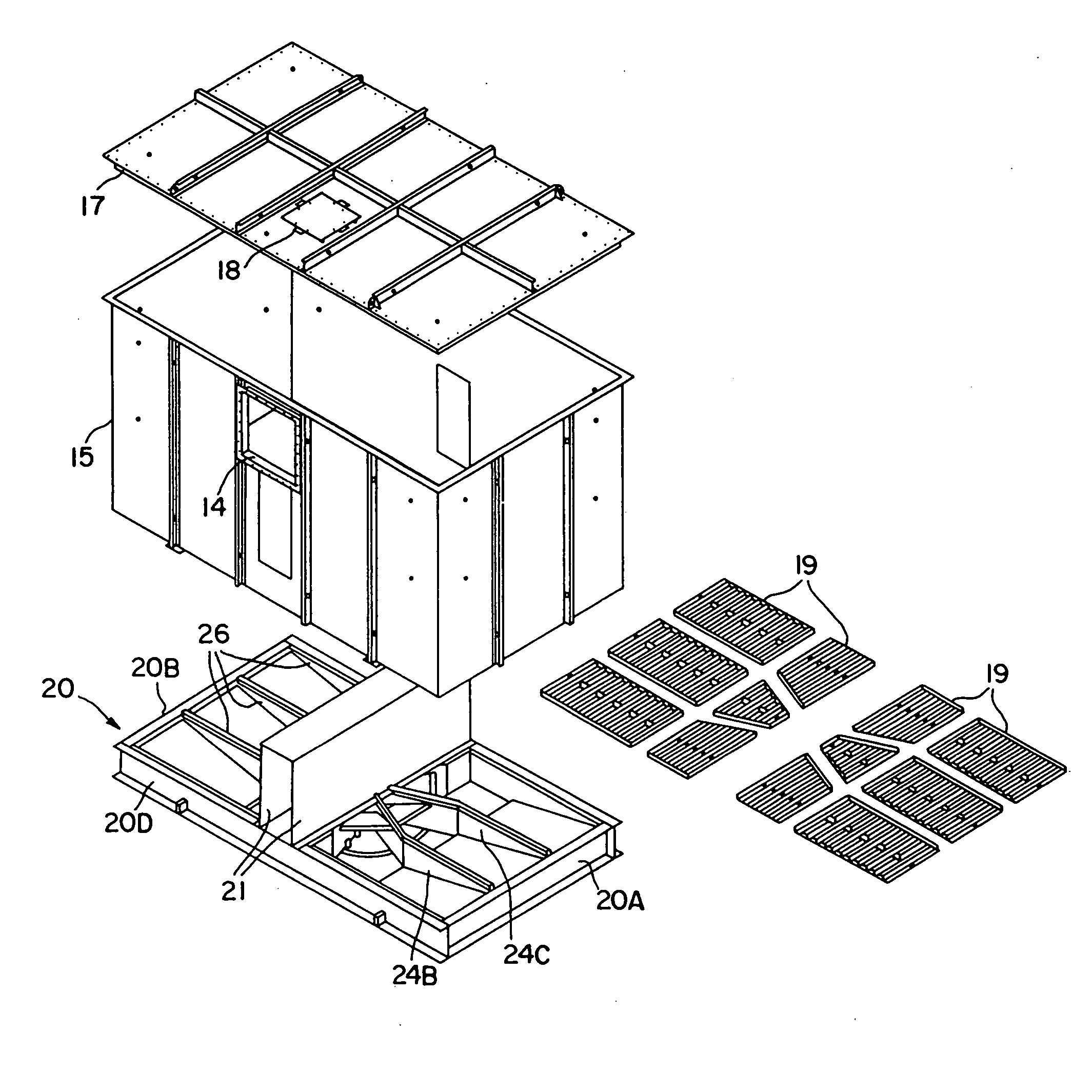
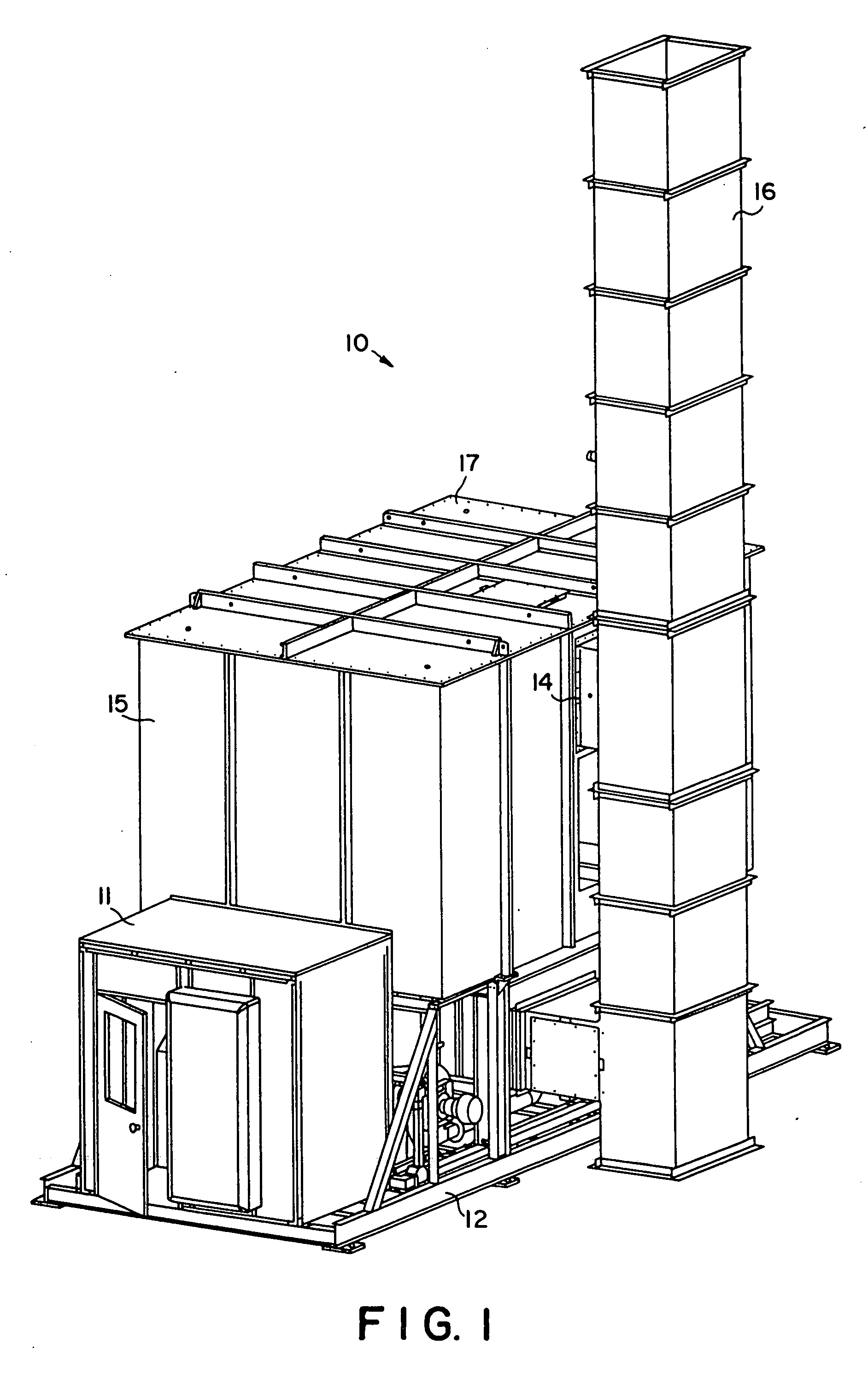
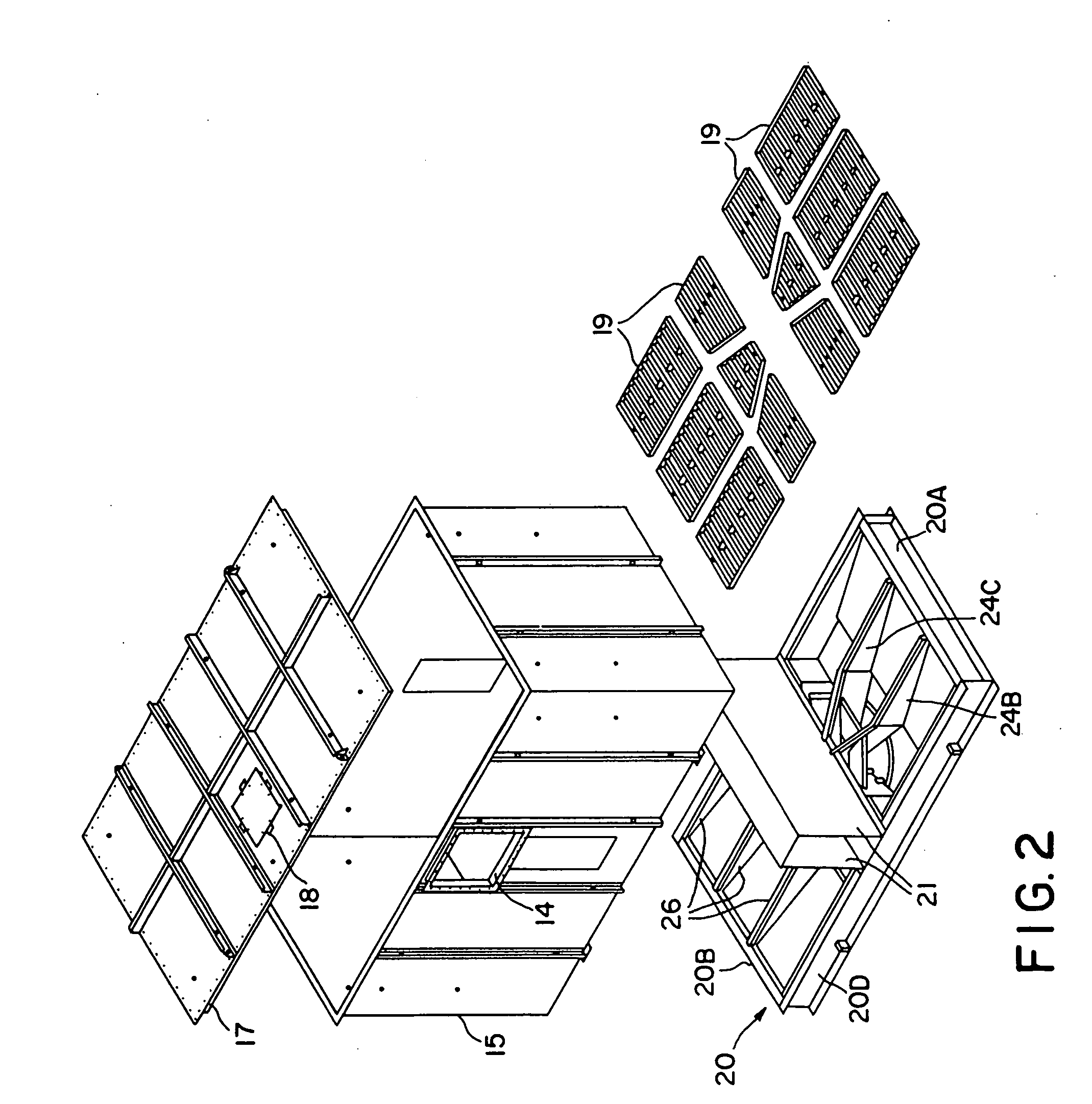
[0041] Familiarity with the valve disclosed in the '092 patent is assumed. Briefly, FIGS. 1 and 2 show a two-chamber regenerative thermal oxidizer 10 (catalytic or non-catalytic) supported on a frame 12 as shown. The oxidizer 10 includes housing 15 in which there are first and second heat exchanger chambers in communication with a centrally located combustion zone. A burner (not shown) may be associated with the combustion zone, and a combustion blower may be supported on the frame 12 to supply combustion air to the burner. The combustion zone includes a bypass outlet 14 in fluid communication with exhaust stack 16 typically leading to atmosphere. A control cabinet ...


PUM


Abstract

Valve with heated sealing gas suitable for use in a regenerative thermal oxidizer, and oxidizer including the switching valve. The valve of the present invention exhibits excellent sealing characteristics and minimizes wear. In a preferred embodiment, the valve utilizes hot gas from the regenerative process to heat gas for sealing the valve, and sealing air flows through a heat exchanger that is positioned to be in contact with hot exhaust gas from the regenerative process.

Description

BACKGROUND OF THE INVENTION [0001] Regenerative thermal oxidizers are conventionally used for destroying volatile organic compounds (VOCs) in high flow, low concentration emissions from industrial and power plants. Such oxidizers typically require high oxidation temperatures in order to achieve high VOC destruction. To achieve high heat recovery efficiency, the “dirty” process gas that is to be treated is preheated before oxidation. A heat exchanger column is typically provided to preheat these gases. The column is usually packed with a heat exchange material having good thermal and mechanical stability and sufficient thermal mass. In operation, the process gas is fed through a previously heated heat exchanger column, which, in turn, heats the process gas to a temperature approaching or attaining its VOC oxidation temperature. This pre-heated process gas is then directed into a combustion zone where any incomplete VOC oxidation is usually completed. The treated now “clean” gas is th...

Claims


Application Information

Patent Timeline
Patent Type & Authority Applications(United States)
IPC IPC(8): F16K1/00F16K1/22F23G7/06F23L15/02F27D7/02F27D17/00F27D99/00
CPCF23L15/02F27D2017/007F27D2007/026F27D99/0073F16K25/02F23G7/068F27D17/008Y02E20/34Y10T137/5689F16K49/005
Inventor CASH, JAMES T.
Owner DURR SYST INC
Why Eureka
Try Eureka