
Budget sensor bus

Inactive Publication Date: 2006-02-23
STANDRD MICROSYSTEMS CORPORATION
View PDF17 Cites 21 Cited by
  • Summary
  • Abstract
  • Description
  • Claims
  • Application Information

AI Technical Summary

Benefits of technology

[0012] Various embodiments of the invention comprise a bus and bus protocol (referred to as Budget Sensor Bus, or BBUS) that can provide a low cost, highly reliable, single pin connection to transmit information from any one of many different device types to any one of many different host types. The transmitted information may include system status, configuration or management data such as CPU type and / or ID, memory size or type, docking type or ID, information about the presence of optional components and ambient light or noise levels, temperature measurements and voltage measurements, among others.
[0013] In one set of embodiments, the BBUS couples a sensor circuit to a host, where data transmission over the BBUS is regulated according to a BBUS bus protocol. The sensor circuit may include up to eight temperature sensors, each temperature sensor operable to provide temperature data indicative of a corresponding measured temperature, and up to eight voltage sensors, each voltage sensor operable to provide voltage data indicative of a corresponding measured voltage. In one embodiment, the BBUS directly transmits raw data bits from any respective sensor in the sensor circuit to the host, and uses a pre-amble to “teach” the host what bit frequency is used by the respective sensor. After the pre-amble, the host may get in sync and may be enabled to directly read the data bits that follow. The BBUS may provide a means for the sensor to immediately transfer temperature conversions to the host.
[0017] Thus, the BBUS provides a more cost effective thermal sensing and / or system management solution, being a single-wire bus implementing a substantially simple protocol, while minimizing required digital circuitry within the sensor circuit (or any other selected monitored circuit) and also minimizing any additional burden on the host device. In one set of embodiments, the BBUS operates as a low speed, reliable management bus that is low cost due to both its implementation and single pin design.

Problems solved by technology

Many digital systems, especially those that include high-performance, high-speed circuits, are prone to operational variances due to temperature effects.
Current implementations of thermal management systems include integrated digital and analog solutions, which typically lack flexibility due to the difficulties encountered with analog signal routing, and stand-alone solutions that provide higher accuracies and route easier, but are generally more expensive.
These features generally result in added digital circuits, affecting the physical layout of IC solutions.
In addition, being coupled to a large number of devices inevitably results in increasing traffic to the SMBus.
The increased traffic leads to an increase in the time required to power up the PC (i.e. extended boot time), and to more complex debugging issues.
The SMBus is also prone to occasional loss of communication and may therefore not provide sufficient reliability for certain management applications.
Integration solutions however typically result in other problems.
It is generally difficult and time consuming to route sensitive analog signals to the chip, and the options for placement of the sensor(s) may also become severely limited.
Ratiometric solutions are also susceptible to noise, typically presenting reliability problems.
While the SensorPath bus offers a single-wire solution, it employs a substantially complicated protocol, making a seamless configuration of a thermal management system with the SensorPath bus relatively difficult.

Method used


Image

  • Budget sensor bus
  • Budget sensor bus
  • Budget sensor bus

Examples


Embodiment Construction

.

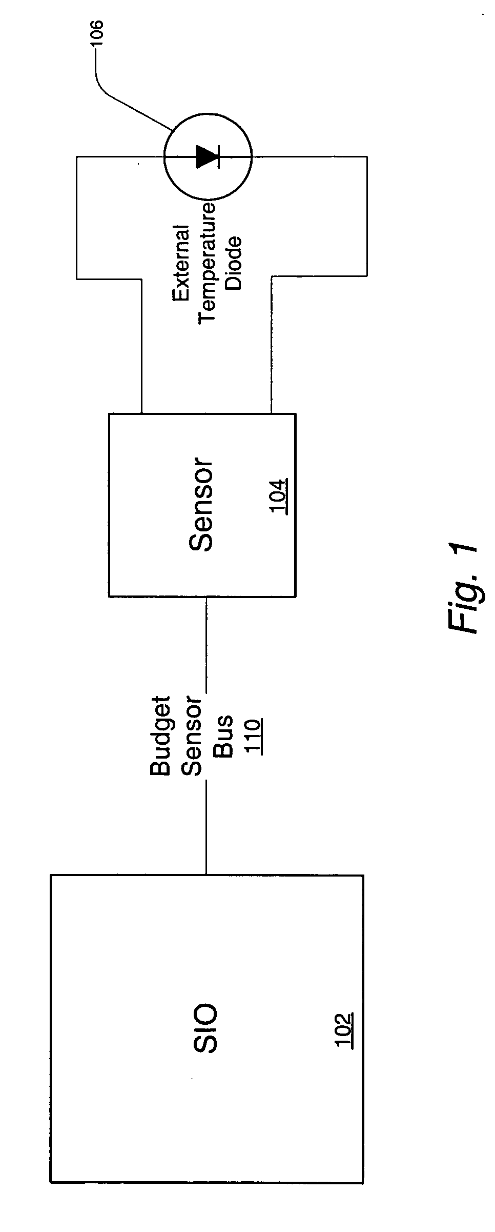
[0031]FIG. 1 illustrates one embodiment of a thermal management system that utilizes the Budget Sensor Bus (BBUS). A sensor circuit 104 may be coupled to Super I / O (SIO) controller device 102 via BBUS 110. In the embodiment of FIG. 1, sensor circuit 104 is used to obtain temperature measurements using external temperature diode 106 coupled to sensor circuit 104. In alternate embodiments, sensor circuit 104 may be used to obtain voltage measurements. Those skilled in the art will appreciate that other system characteristics besides temperature and / or voltage may also be measured, and that sensor circuit 104 may be configured accordingly to obtain the data corresponding to these system characteristics. In one set of embodiments, BBUS 110 comprises a single-wire bus protocol configured to transmit packets of information in Non-Return to Zero (NRZ) format. NRZ encoding may be used to represent the binary bit-value ‘1’ by a positive or higher voltage, and the binary bit-value ‘0’ by a l...


PUM


Abstract

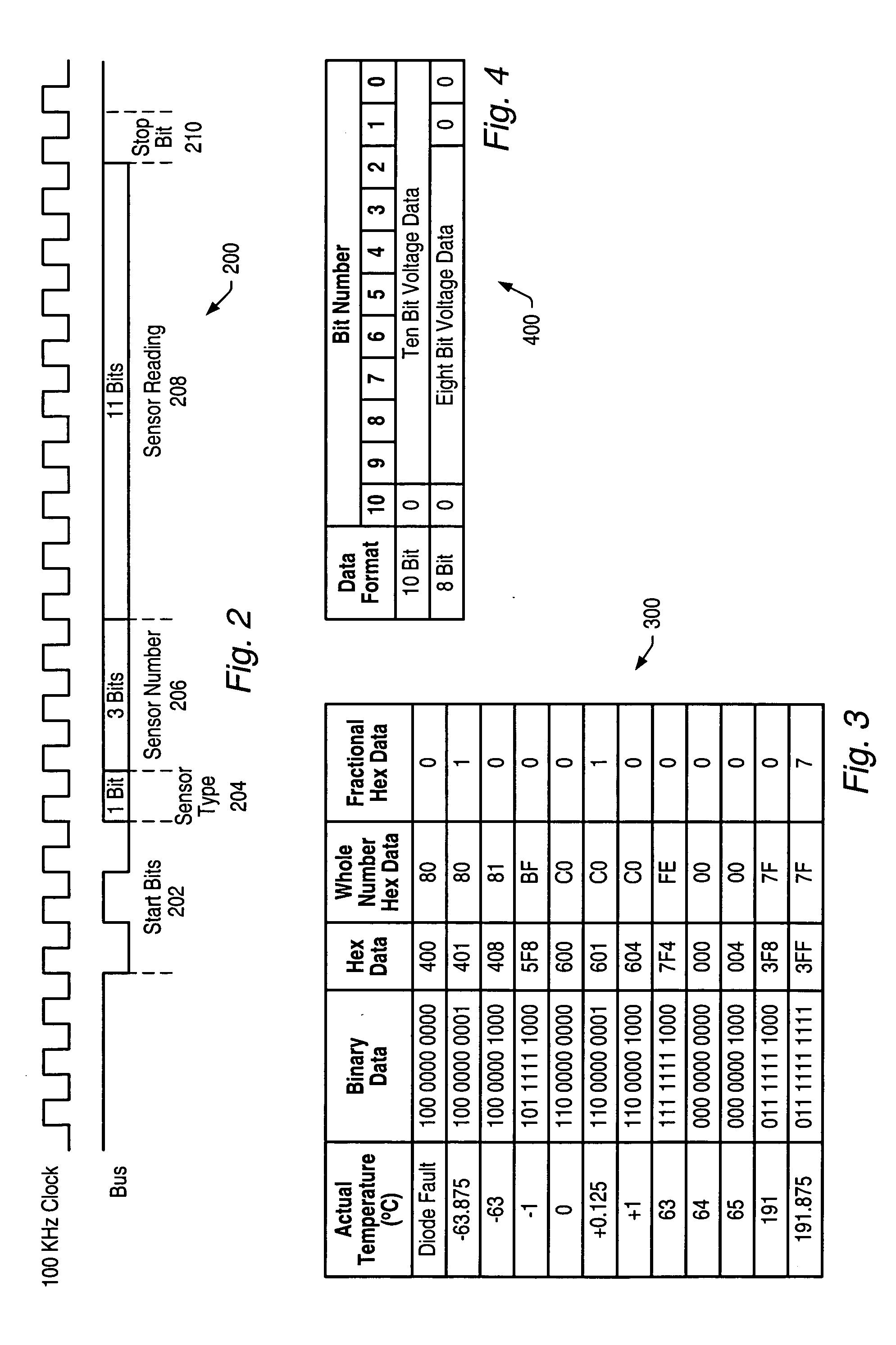
A single-wire bus protocol named Budget Sensor Bus (BBUS) for simplified system management. The BBUS may transmit information packets in NRZ format from a monitored device / circuit to a host. In one embodiment, each packet comprises a start sequence, a data type, a device or register number, device data, and a stop sequence. The BBUS may directly transmit raw data bits from the monitored device / circuit to the host and may use the start sequence to communicate to the host the bit frequency that is used by the monitored device / circuit. Following the start sequence the host may get in sync with the monitored device / circuit and may be enabled to directly read the data bits that follow. The BBUS may provide a means for the monitored device / circuit to immediately transfer device information to the host. All functions and operations required to interpret the device information may reside within the host. The BBUS may transmit information packets from the monitored device / circuit to the host, but not from the host to the monitored device / circuit. In one embodiment the BBUS is used for thermal management, where the monitored device / circuit comprises temperature / voltage sensors, the host is an SIO controller, and temperature / voltage data is transmitted from the sensors to the SIO controller.

Description

BACKGROUND OF THE INVENTION [0001] 1. Field of the Invention [0002] This invention relates generally to the field of digital interface design and, more particularly, to bus interface design. [0003] 2. Description of the Related Art [0004] Many digital systems, especially those that include high-performance, high-speed circuits, are prone to operational variances due to temperature effects. This presents a need to implement thermal management and control in many of those systems. Devices that monitor temperature and voltage are often included in order to perform the required thermal management / control, and thus maintain the integrity of the system components. Personal computers (PC), signal processors and high-speed graphics adapters, among others, typically benefit from such thermal management circuits. For example, a central processor unit (CPU) that typically “runs hot” as its operating temperature reaches high levels may require a temperature sensor in the PC to insure that it do...

Claims


Application Information

Patent Timeline
IPC IPC(8): H04J3/16
CPCG06F1/206H04L7/04G06F13/4282
Inventor WORTEL, KLAASWAHLER, RICHARD E.LUECK, ANDREW W.
Owner STANDRD MICROSYSTEMS CORPORATION
Learn More