Flexible plastic container

Inactive Publication Date: 2005-10-20
SMITH MARK A +1
View PDF4 Cites 10 Cited by
  • Summary
  • Abstract
  • Description
  • Claims
  • Application Information

AI Technical Summary

Problems solved by technology

Both gravity dispensing bags and vacuum pump systems suffer from the common drawback that fluid may become trapped within the folds of the bag during draining.
As the bag is emptied by the force of the vacuum pump, or by the force of gravity, portions of the bag collapse unevenly, tending to leave pockets of product, typically liquid, which may become isolated from the rest of the liquid in the container.
The evacuation channel, however, forms a conduit which cannot be closed off by the folds created in the bag.
Several problems have been encountered with these types of evacuation units.
For example, during the filling process, which is typically done in a high speed and high pressure process, the evacuation unit is susceptible of being dislodged from the spout thereby rendering the evacuation unit inoperative.
Also, the attaching ring can impede the flow of liquid during the filling process thereby slowing the filling process.
Because the evacuation unit is positioned in a location that is in line with the incoming fluid during the filling process, it is susceptible of being dislodged from its mounting to the container thereby rendering it ineffective.
This is highly undesirable because it adds another step to the manufacturing process and increases the labor costs.

Method used


Image

  • Flexible plastic container
  • Flexible plastic container
  • Flexible plastic container

Examples


Embodiment Construction

[0021] While this invention is susceptible of embodiment in many different forms, herein will be described in detail with the accompanying figures, a preferred embodiment of the invention. The present disclosure is to be considered as an exemplification of the principles of the invention and is not intended to limit the broad aspect of the invention to the embodiments illustrated and described.

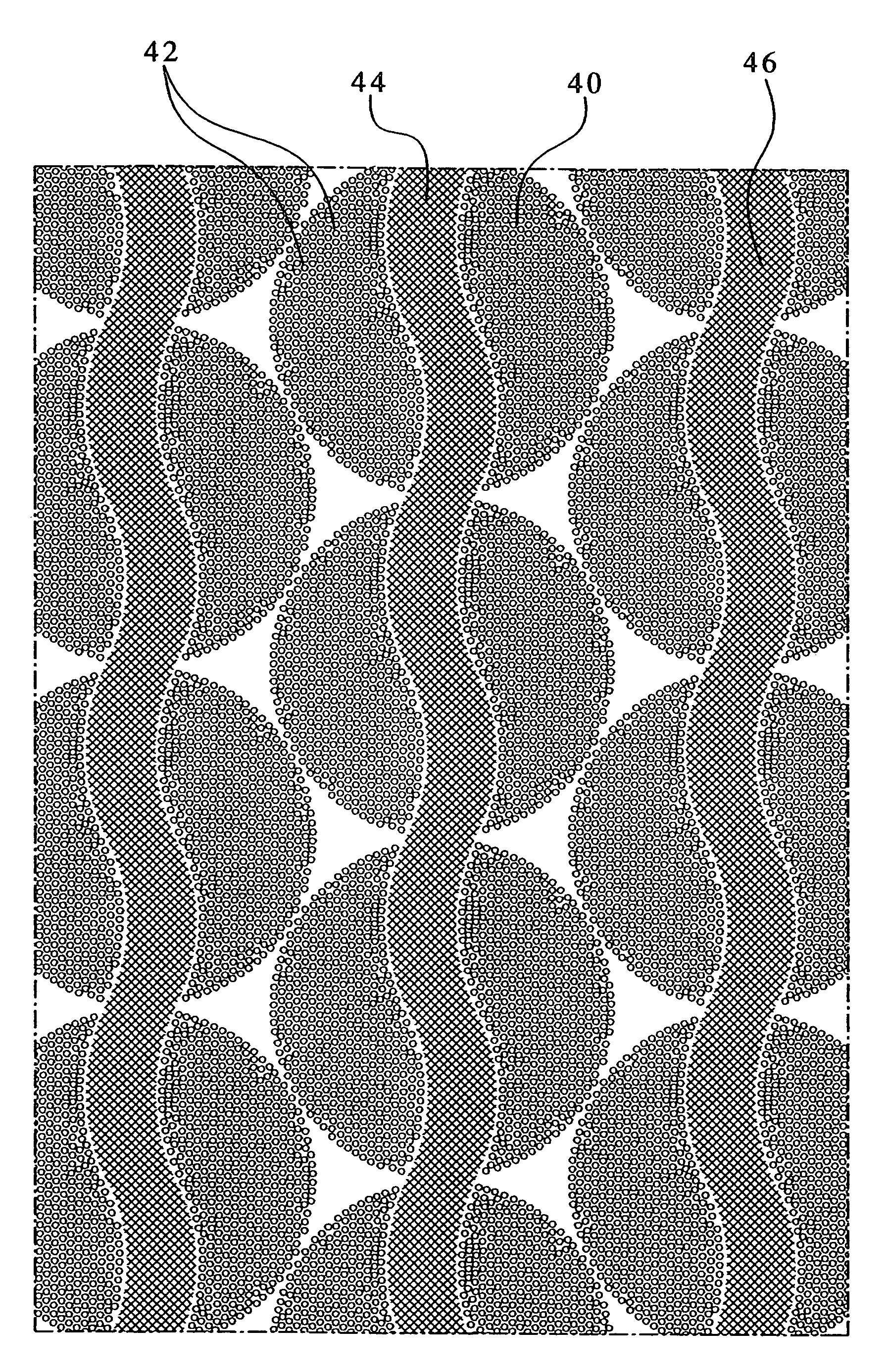
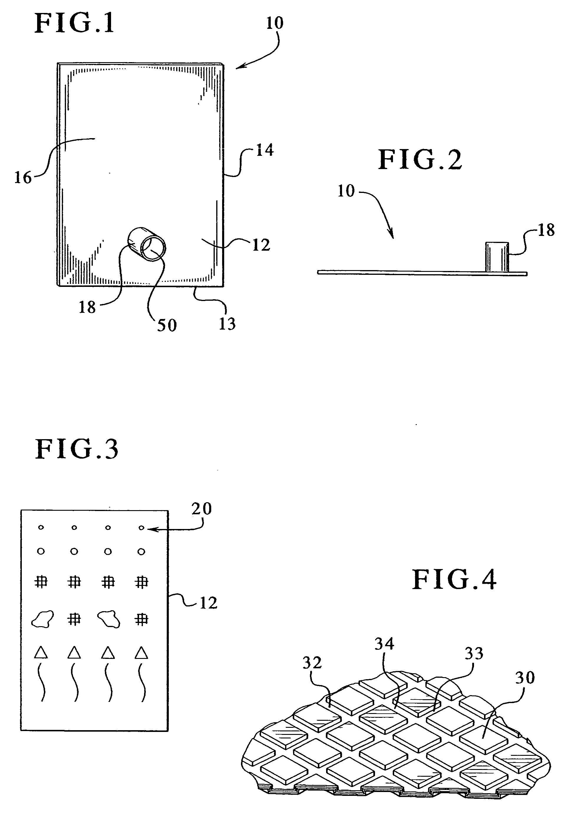
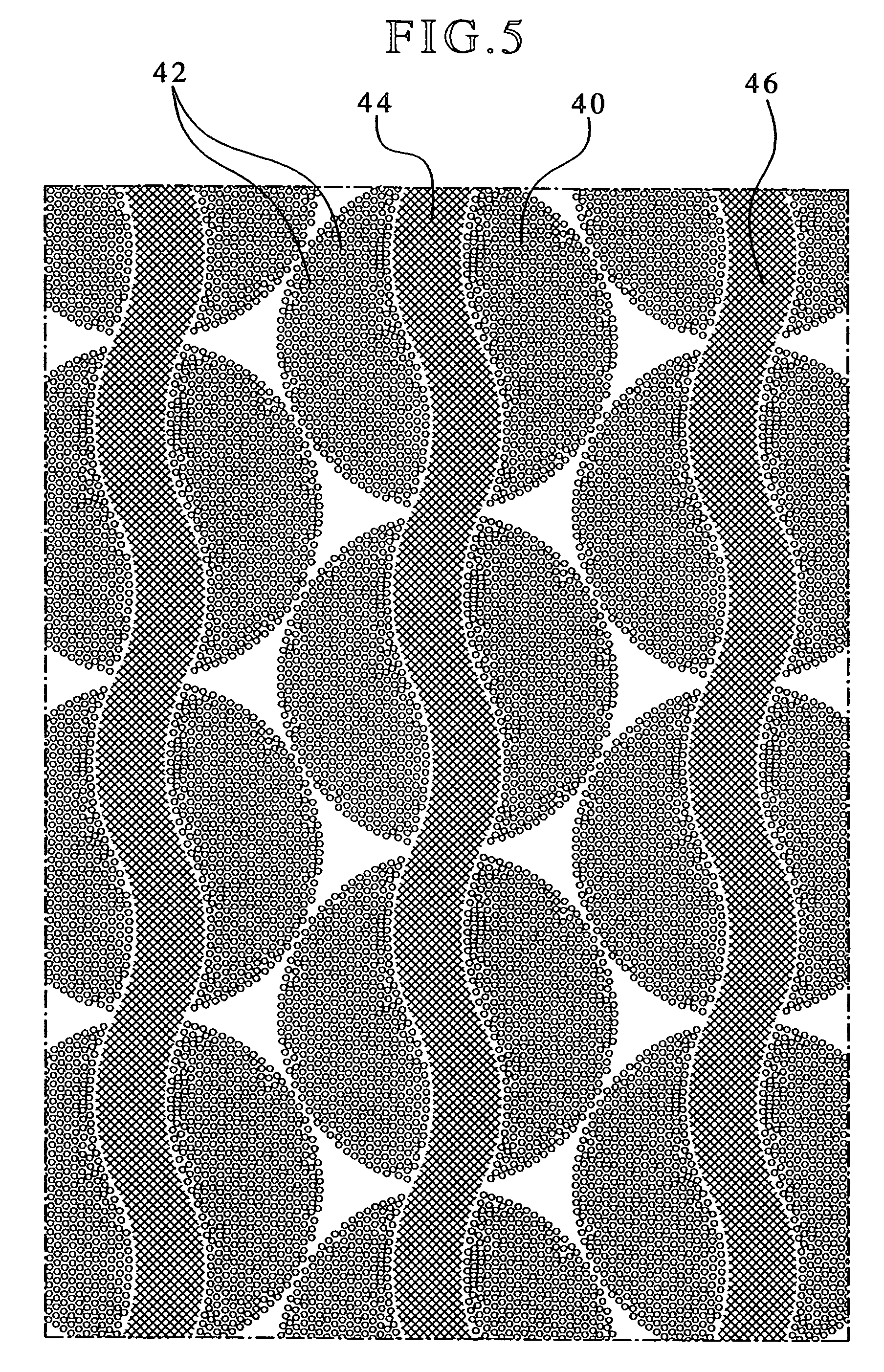
[0022]FIGS. 1 and 2 show a flexible container assembly 10 having a first sidewall 12 and a second sidewall 13 attached at peripheral edges 14 to define a fluid tight chamber 16. A spout 18 is attached to an outer surface of the sidewall 12 and provides fluid flow access to the chamber 16. In a preferred form of the invention, the first and second sidewalls 12 and 13 are a flexible polymeric material having a modulus of elasticity of less than 50,000 psi. The sidewalls preferably are made from materials such as homopolymers and copolymers of polyolefins, polyamides, polyesters or other materia...


PUM

PropertyMeasurementUnit
Lengthaaaaaaaaaa
Lengthaaaaaaaaaa
Depthaaaaaaaaaa

Abstract

A flexible polymeric container for storing and dispensing liquids includes a first sidewall and a second sidewall connected together to define a fluid chamber therebetween. The first sidewall and the second sidewall each have an inner surface facing the fluid chamber and an opposed outer surface. A fitment is attached to an outer surface of one of the first sidewall or the second sidewall. The fitment has an opening therethrough which has an axis substantially perpendicular to the outer surface. A plurality of objects on the inner surface of one of the first sidewall or the second sidewall defines a plurality of pathways having at least a first pathway and a second pathway intersecting one another.

Description

RELATED APPLICATIONS [0001] This application is a continuation-in-part of U.S. patent application Ser. No. 10 / 291,344 filed on Nov. 8, 2002, which is a continuation-in part of U.S. patent application Ser. No. 10 / 037,295 filed on Dec. 21, 2001 which claims priority from Provisional Patent Application Ser. No. 60 / 332,463 filed on Nov. 9, 2001.TECHNICAL FIELD [0002] The present invention relates generally to a flexible plastic container and more particularly to a flexible container for directing a flowable material contained therein to a fitment of the container and dispensing the flowable material. BACKGROUND OF THE INVENTION [0003] Collapsible plastic bags are often used to store liquid products such as chemicals, soft drink syrup, fruit juices and food condiments. The plastic bags are typically housed in a corrugated paperboard box to aid in the transporting, handling and dispensing of the product. Such packaging systems are commonly referred to as “bag-in-box” packaging systems. [0...

Claims


Application Information

Patent Timeline
IPC IPC(8): B65D33/36B65D35/02B65D35/08B65D35/14B65D35/16B65D35/28B65D35/54B65D35/56B65D77/06
CPCB65D75/5877B65D2231/002B65D77/065B65D77/062
Inventor SMITH, MARK A.WILFORD, MICHAEL
Owner SMITH MARK A
Why Eureka
Try Eureka