Liquid metal processing and dispensing for liquid metal devices

Inactive Publication Date: 2005-10-20
AGILENT TECH INC
View PDF11 Cites 5 Cited by
  • Summary
  • Abstract
  • Description
  • Claims
  • Application Information

AI Technical Summary

Benefits of technology

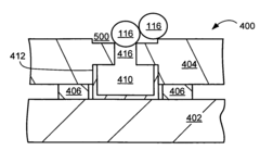
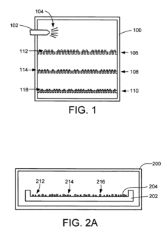
[0007] The present invention provides a method for manufacturing a liquid metal device. Liquid metal is solidified into solid metal balls. The solid metal balls are collected adjacent an opening in the liquid metal device. The solid metal balls are liquefied into liquid metal to flow into the opening. This results in a simple and inexpensive liquid metal forming system and a dispensing system for manufacturing a liquid metal device having a compact and relatively simple structure, but also has high operating reliability and a long service life.

Problems solved by technology

The reed relay has problems related to its large size and relatively short service life.
As to the first problem, the reeds not only require a relatively large space, but also do not perform well during high frequency switching due to their size and electromagnetic response.
As to the second problem, the flexing of the reeds due to biasing and attraction causes mechanical fatigue, which can lead to breakage of the reeds after extended use.
However, these contacts would fail over time.
This solved the problem of contact failure, but the problem of mechanical fatigue of the reeds remained unsolved.
However, as device sizes have been reduced, it has become more and more difficult to provide the proper amounts of the liquid metal into the main channels where the liquid metal may be separated by the application of pressurized non-conductor fluid.
Solutions to these problems have been long sought but have long eluded those skilled in the art.

Method used


Image

  • Liquid metal processing and dispensing for liquid metal devices
  • Liquid metal processing and dispensing for liquid metal devices
  • Liquid metal processing and dispensing for liquid metal devices

Examples


Embodiment Construction

[0022] In the following description, numerous specific details are given to provide a thorough understanding of the invention. However, it will apparent that the invention may be practiced without these specific details. In order to avoid obscuring the present invention, some well-known system configurations and process steps are not disclosed in detail.

[0023] The term “horizontal” as used herein is defined as a plane parallel to the conventional plane or surface of the first substrate, regardless of its orientation. The term “vertical” refers to a direction perpendicular to the horizontal as just defined. Terms, such as “on”, “above”, “below”, “bottom”, “top”, “over”, and “under”, are defined with respect to the horizontal plane.

[0024] Likewise, the drawings showing embodiments of the invention are semi-diagrammatic and not to scale and, particularly, some of the dimensions are for the clarity of presentation and are shown greatly exaggerated in the FIGs. In addition, where multi...


PUM

PropertyMeasurementUnit
Temperatureaaaaaaaaaa
Pressureaaaaaaaaaa
Flow rateaaaaaaaaaa

Abstract

A method is provided for manufacturing a liquid metal device. Liquid metal is solidified into solid metal balls. The solid metal balls are collected adjacent an opening in the liquid metal device. The solid metal balls are liquefied into liquid metal to flow into the opening.

Description

BACKGROUND [0001] A reed relay is a typical example of a conventional small, mechanical contact type of electrical switch device. A reed relay has two reeds made of a magnetic alloy sealed in an inert gas inside a glass vessel surrounded by an electromagnetic driver coil. When current is not flowing in the coil, the tips of the reeds are biased to break contact and the device is switched off. When current is flowing in the coil, the tips of the reeds attract each other to make contact and the device is switched on. [0002] The reed relay has problems related to its large size and relatively short service life. As to the first problem, the reeds not only require a relatively large space, but also do not perform well during high frequency switching due to their size and electromagnetic response. As to the second problem, the flexing of the reeds due to biasing and attraction causes mechanical fatigue, which can lead to breakage of the reeds after extended use. [0003] In the past, the r...

Claims


Application Information

Patent Timeline
IPC IPC(8): B22D21/00H01H11/02H01H29/22H01H29/28H01H29/30H02N2/00
CPCB22D21/007H01H29/28H01H11/02
InventorFAZZIO, RONALD SHANE
OwnerAGILENT TECH INC