
Connection arrangement for connecting an anaesthetic container to an anaesthetic vaporizer

Pending Publication Date: 2021-09-23
DRAGERWERK AG
View PDF0 Cites 0 Cited by
  • Summary
  • Abstract
  • Description
  • Claims
  • Application Information

AI Technical Summary

Benefits of technology

The present invention is a connection device that connects an anesthetic container to an anesthetic vaporizer in a fluid-tight manner. The device has a higher operational reliability than prior art devices, making it easier to fill the vaporizer with anesthetic. The technical effect of the invention is to provide a more reliable and efficient connection between the anesthetic container and the anesthetic vaporizer.

Problems solved by technology

“Without intermediate space” means that the volume of such an intermediate space is negligibly small, i.e., it cannot hold a relevant quantity of fluid.
The frequently used anesthetic desflurane has a boiling point of about 23° C. The escape of anesthetic into the environment is undesired.
Because the contact surfaces are in contact with one another without an intermediate space, it is also unnecessary in many cases to use a seal in order to seal such an intermediate space against anesthetic.
Sealants resistant to anesthetics are often expensive.
Such a projecting part may lead to an injury or be damaged.
Conversely, the application of a force to the adjusting device causes the adjusting device to move away from the head.
A projection in the adapter could be pushed in unintentionally, without the adapter being connected to the port section, which causes the container-side channel section to be opened and anesthetic to flow out or otherwise to escape into the environment, which is undesirable.
Such a seal may wear off or be attacked by the anesthetic.
In addition, compared to an adapter made of metal, metal-on-metal contact is prevented, and such a contact is often undesired.
However, at least one channel section is still blocked in the coupled state, so that no anesthetic can flow.

Method used


Image

  • Connection arrangement for connecting an anaesthetic container to an anaesthetic vaporizer
  • Connection arrangement for connecting an anaesthetic container to an anaesthetic vaporizer
  • Connection arrangement for connecting an anaesthetic container to an anaesthetic vaporizer

Examples


Embodiment Construction

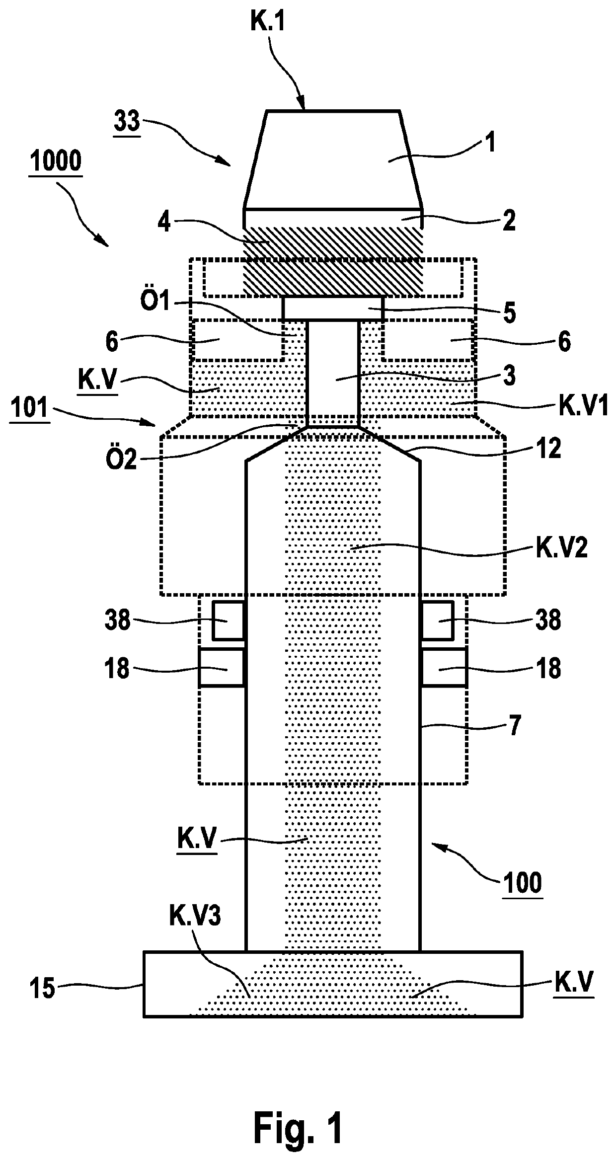
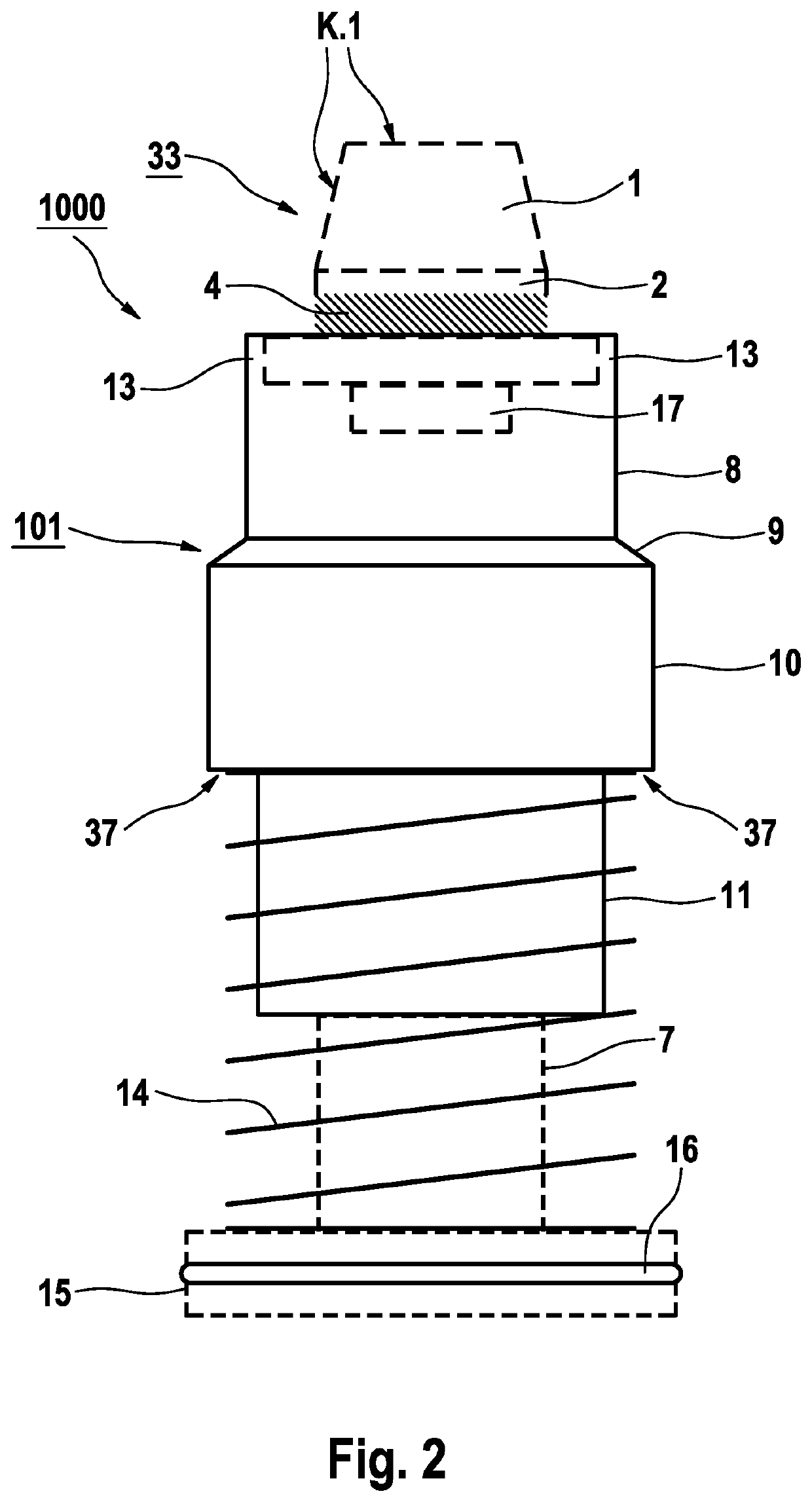
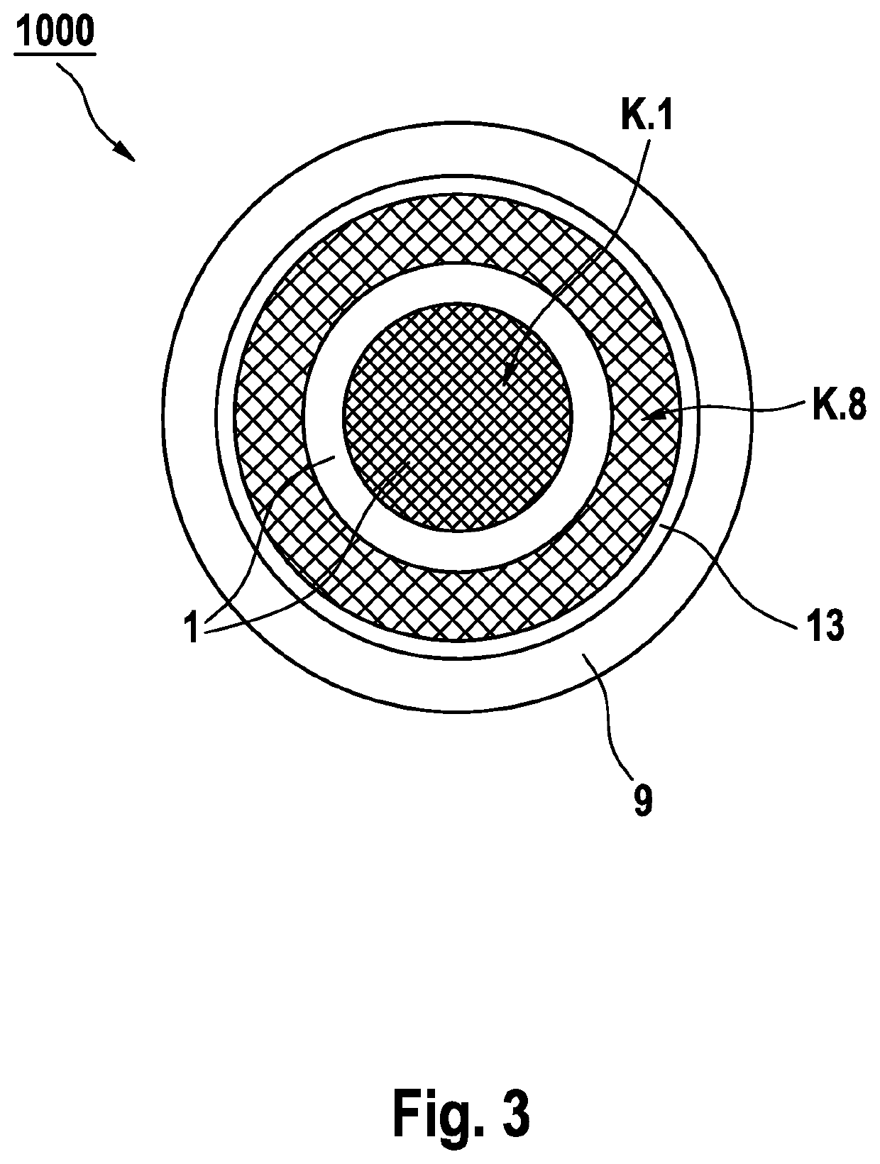
[0074]Referring to the drawings, the connection device according to the exemplary embodiment comprises a port section 1000, which is inserted into an anesthetic vaporizer 300, and an adapter 1100, which is inserted into an anesthetic container 400. The port section 1000 according to the exemplary embodiment comprises an inner vaporizer-side component 100 and an outer vaporizer-side component 101. FIG. 1 through FIG. 5 show a first embodiment of the port section 1000 of the anesthetic vaporizer 300. FIG. 1 and FIG. 2 show the inner vaporizer-side component 100 and the outer vaporizer-side component 101, respectively, in a cross-sectional view through the central axis of the rotationally symmetrical port section 1000. The outer vaporizer-side component 101 is indicated by dotted lines in FIG. 1. The inner vaporizer-side component 100 is indicated by broken lines in FIG. 2. FIG. 3 and FIG. 4 show the port section 1000 in a viewing direction from the top and parallel to the central axis...


PUM


Abstract

A connection device allows connection of an anesthetic container (400) to an anesthetic vaporizer (300) in a fluid-tight manner. A port section (1000) of the anesthetic vaporizer can be detachably connected to an adapter (1100) of the port section. With the adapter connected to the port section, a vaporizer-side channel section and a container-side channel section together form a continuous channel for anesthetic. The area of the surface of the port section that points towards the adapter is formed by a vaporizer-side contact profile (K.1, K.8), and the area of the surface of the adapter that points towards the port section is formed by a container-side contact profile (K.25, 28, 31). One contact profile has a projection (1), and the other contact profile has a corresponding recess (25) that contact with one another without an intermediate space. The projection positive-lockingly meshes with the recess.

Description

CROSS REFERENCE TO RELATED APPLICATIONS[0001]This application is a United States National Phase Application of International Application PCT / EP2019 / 069487, filed Jul. 19, 2019, and claims the benefit of priority under 35 U.S.C. § 119 of German Application 10 2018 006 264.4, filed Aug. 8, 2018, the entire contents of which are incorporated herein by reference.TECHNICAL FIELD[0002]The present invention pertains to a connection device, which is capable of detachably connecting an adapter of an anesthetic container to a port section of an anesthetic vaporizer and makes it possible thereby for anesthetic to flow from the anesthetic container into the anesthetic vaporizer, as well as to an anesthetic vaporizer and to an anesthetic adapter. An anesthesia device supplies a patient with a mixture of air or another gas and evaporated anesthetic. A previously liquid anesthetic is evaporated in an anesthetic vaporizer by being heated, for example, to about 40° C., and is mixed with the gas. Suc...

Claims


Application Information

Patent Timeline
IPC IPC(8): A61M16/18
CPCA61M16/186A61M16/183
Inventor ZECHLIN, JACOB-MICHAELBUCHHOLZ, MORITZPRIOR, DAISYFIELDING, LUCYKRÖPLIN, THOMAS
Owner DRAGERWERK AG
Learn More