
Lighting apparatus having high operation reliability and lighting system using the same

Active Publication Date: 2012-09-13
AU OPTRONICS CORP
View PDF1 Cites 0 Cited by
  • Summary
  • Abstract
  • Description
  • Claims
  • Application Information

AI Technical Summary

Benefits of technology

[0006]In accordance with the embodiment, a lighting system having high operation reliability is further provided. The lighting system comprises a driving voltage providing circuit for providing a driving voltage, a first lighting unit with a first turn-on voltage, a second lighting unit with a second turn-on voltage greater than the first turn-on voltage, and a driving current control circuit electrically connected to the first and second lighting units. The second turn-on voltage is less than the driving voltage. The first lighting unit, electrically connected to the driving voltage providing circuit for receiving the driving voltage, is utilized for generating output light having a first brightness according to a driving current. The second lighting unit, electrically connected in parallel with the first lighting unit and electrically connected to the driving voltage providing circuit for receiving the driving voltage, is utilized for generating output light having a second brightness according to the driving current. The second brightness is preferably identical to the first brightness. The driving current control circuit is employed to control the driving current flowing through the first lighting unit or the second lighting unit.

Problems solved by technology

In view of that, if one of the LEDs is broken off due to a burned-out event, other LEDs serially connected with the broken LED are unable to work accordingly.
That is, the lighting operation of prior-art LED lighting system is hard to reach high reliability.

Method used


Image

  • Lighting apparatus having high operation reliability and lighting system using the same
  • Lighting apparatus having high operation reliability and lighting system using the same
  • Lighting apparatus having high operation reliability and lighting system using the same

Examples


first embodiment

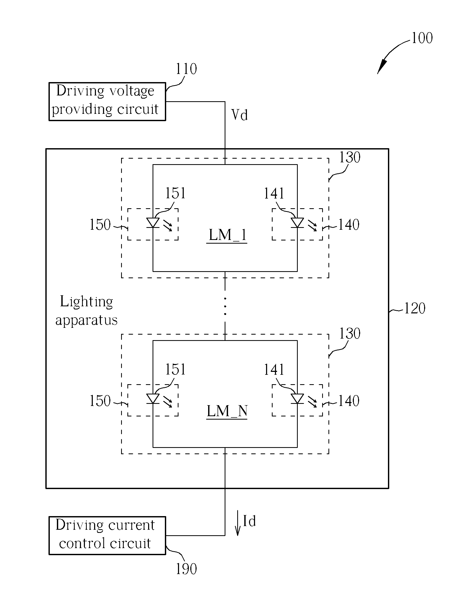
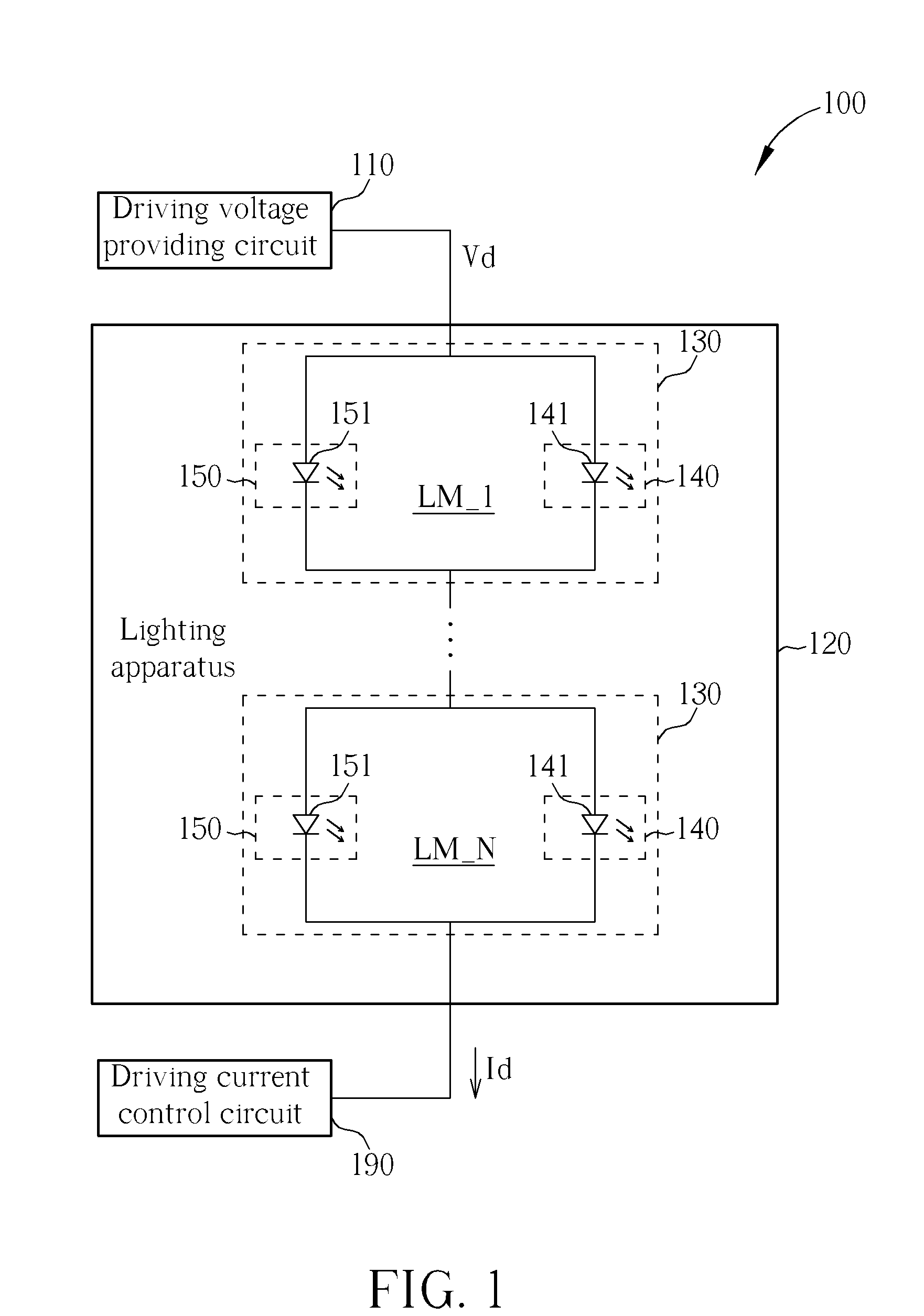
[0014]FIG. 1 is a schematic diagram showing a lighting system in accordance with a As shown in FIG. 1, the lighting system 100 comprises a driving voltage providing circuit 110, a driving current control circuit 190, and a lighting apparatus 120 electrically connected between the driving voltage providing circuit 110 and the driving current control circuit 190. The driving voltage providing circuit 110 is employed to provide a driving voltage Vd. The driving current control circuit 190 is employed to control a driving current Id flowing through the lighting apparatus 120. The lighting apparatus 120 includes a plurality of lighting modules 130 electrically connected in series. Each of the lighting modules 130 comprises a first lighting unit 140 with a first turn-on voltage and a second lighting unit 150 with a second turn-on voltage greater than the first turn-on voltage. The second lighting unit 150 is electrically connected in parallel with the first lighting unit 140. The sum of ...

second embodiment

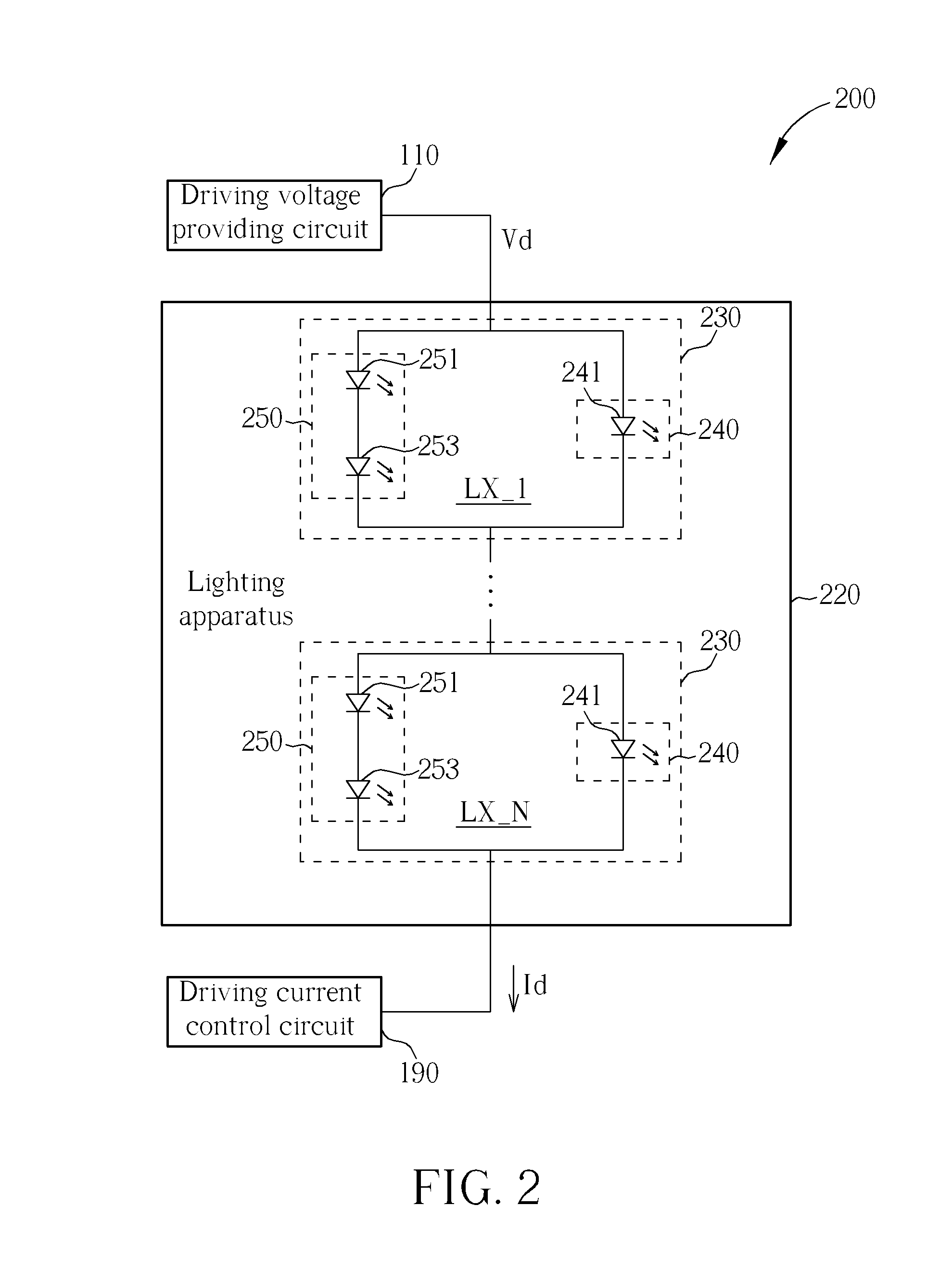
[0017]FIG. 2 is a schematic diagram showing a lighting system in accordance with a As shown in FIG. 2, the lighting system 200 comprises the driving voltage providing circuit 110, the driving current control circuit 190, and a lighting apparatus 220 electrically connected between the driving voltage providing circuit 110 and the driving current control circuit 190. The lighting apparatus 220 includes a plurality of lighting modules 230 electrically connected in series. Each of the lighting modules 230 comprises a first lighting unit 240 with a first turn-on voltage and a second lighting unit 250 with a second turn-on voltage greater than the first turn-on voltage. The second lighting unit 250 is electrically connected in parallel with the first lighting unit 240. The sum of the second turn-on voltages of the second lighting units 250 in the lighting apparatus 220 is less than the driving voltage Vd. In one embodiment, the first lighting unit 240 and the second lighting unit 250 of ...

third embodiment

[0020]FIG. 3 is a schematic diagram showing a lighting system in accordance with a As shown in FIG. 3, the lighting system 300 comprises the driving voltage providing circuit 110, the driving current control circuit 190, and a lighting apparatus 320 electrically connected between the driving voltage providing circuit 110 and the driving current control circuit 190. The lighting apparatus 320 includes a plurality of lighting modules 330 electrically connected in series. Each of the lighting modules 330 comprises a first lighting unit 340 with a first turn-on voltage and a second lighting unit 350 with a second turn-on voltage greater than the first turn-on voltage. The second lighting unit 350 is electrically connected in parallel with the first lighting unit 340. The sum of the second turn-on voltages of the second lighting units 350 in the lighting apparatus 320 is less than the driving voltage Vd. In one embodiment, the first lighting unit 340 and the second lighting unit 350 of ...


PUM


Abstract

A lighting apparatus having high operation reliability includes a first lighting unit with a first turn-on voltage and a second lighting unit with a second turn-on voltage greater than the first turn-on voltage. The lighting apparatus is put in use for generating output light according to a driving current flowing through the first lighting unit or the second lighting unit. The first lighting unit is capable of generating output light having a first brightness according to the driving current. The second lighting unit, electrically connected in parallel with the first lighting unit, is capable of generating output light having a second brightness according to the driving current. The second brightness is preferably identical to the first brightness.

Description

BACKGROUND[0001]1. Technical Field[0002]The description relates to a lighting apparatus, and more particularly, to a lighting apparatus having high operation reliability and related lighting system using the same.[0003]2. Description of the Related Art[0004]Light emitting diodes (LEDs) have advantages of lightweight, small size, low power consumption and high-bright lighting capability, and are broadly adopted for use in a variety of indication applications, indoor or outdoor lighting applications, vehicle auxiliary lighting applications, camera flashlights, and so forth. Besides, the backlight sources of liquid crystal displays are switched from traditional cold cathode fluorescent lamps (CCFLs) or external electrode fluorescent lamps (EEFLs) to LED lighting apparatuses gradually. In general, the lighting apparatus of an LED lighting system is formed by plural LEDs connected in series. In view of that, if one of the LEDs is broken off due to a burned-out event, other LEDs serially ...

Claims


Application Information

Patent Timeline
IPC IPC(8): H05B37/02H05B44/00
CPCH05B33/0845H05B33/0806H05B45/10H05B45/00
Inventor WANG, CHING-HUNGHSU, SHENG-KAI
Owner AU OPTRONICS CORP
Learn More