Dental targetting device and method

a technology for teeth and target teeth, applied in dental tools, dental surgery, medical science, etc., can solve the problems of difficult to properly position the bracket on the lingual surface, less accurate bracket placement may require repeated treatments, and many efforts to ensur

Active Publication Date: 2005-10-20
ALIGN TECH
View PDF25 Cites 156 Cited by
  • Summary
  • Abstract
  • Description
  • Claims
  • Application Information

AI Technical Summary

Problems solved by technology

Conversely, less accurate placement of brackets may require repeated treatments, including repeated bonding and wire bending procedures until the final alignment is achieved.
Thus, during the process of placing the brackets on the teeth, much effort is made to ensure the accurate positioning of the brackets in accordance with their desired position as determined by the treatment plan.
However, by current methods it is difficult to properly position the brackets on the lingual surfaces, particularly in view of difficulties in monitoring the position during attachment of the brackets.
The difficulty with manual orthodontic procedures, as commonly practiced nowadays, is that they are subject to human error.
In the first place, it is very hard to place the bracket where it is desired to be located.
Another common difficulty relates to the disengagement of the bracket from the positioning tool, as this process typically causes a slight movement of the bracket on the tooth due to inherent and uncontrolled small human movements.
This difficulty is compounded when the orthodontist must place brackets not only on buccal tooth surfaces but also on lingual surfaces.
With existing methods, it is not easy for an orthodontist to properly position brackets on lingual surfaces.
Most of the preparatory work is done by a technician rather than the dentist, and the technique results in a shorter installation time than when the brackets are installed manually one at a time, but the technician needs to have a supply of brackets readily available.
On the other hand, should one or more of the brackets move during installation, or not be fixed properly onto the teeth, it has to be reset manually without the aid of the tray.
In practice, many failures occur due to the imperfect fit between the tray and the teeth, resulting in part due to the dimensional differences between the plaster model and the actual teeth.
As with the traditional indirect bonding technique, dimensional inaccuracies between the model and the real teeth can lead to inaccurate placement.

Method used


Image

  • Dental targetting device and method
  • Dental targetting device and method
  • Dental targetting device and method

Examples


first embodiment

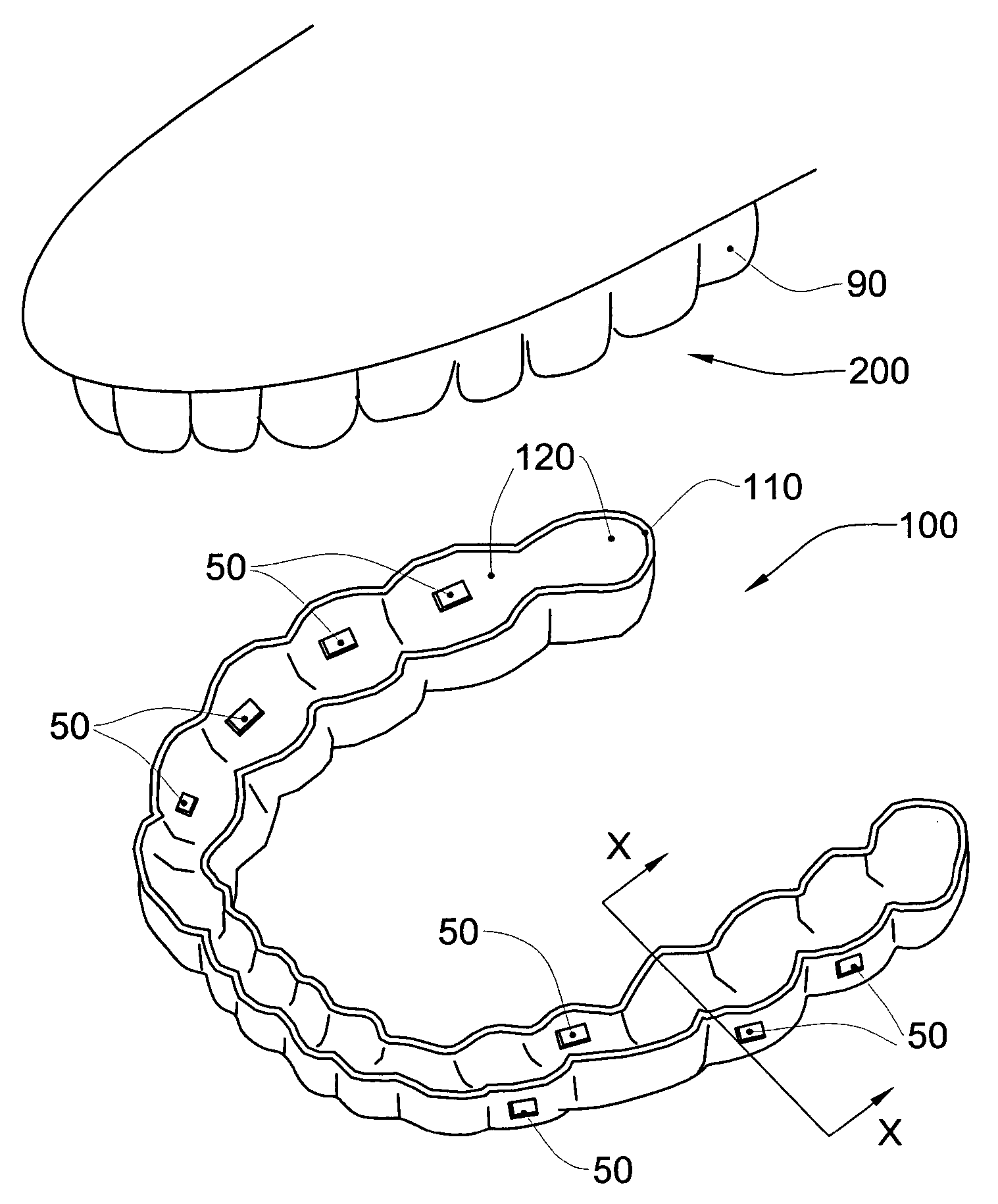
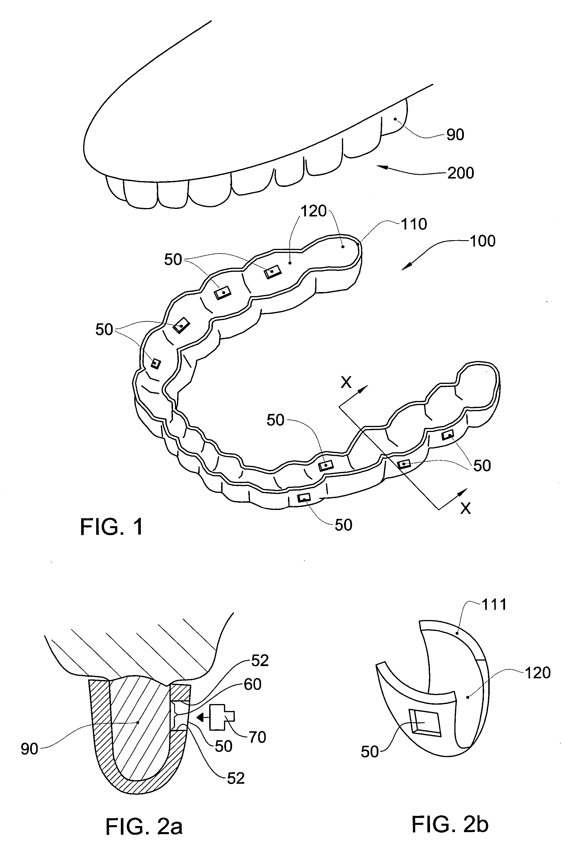
[0065] Referring to FIG. 1, the present invention comprises a dental targeting device in the form of a tray, generally designated with the numeral 100, having a plurality of windows 50. The tray 100 comprises a U-shaped shell 110 having a plurality of cavities 120 which are shaped to receive teeth. As described in greater detail herein, the tray 100 is designed to fit over an arch 200 regarding which it is desired to provide an orthodontic treatment to at least some of the teeth therein. Thus, the inside shape of each of the cavities 120 is substantially complementary to the external shape of the particular tooth of the arch 200 that is received therein, in particular the lingual and buccal / labial surfaces of the teeth. Accordingly, the tray 100 is designed to fit over the teeth in their current positions, and does not itself require to exert any alignment forces on the teeth, even if manufactured from an elastic material.

[0066] In this embodiment, when the tray 100 is properly seat...

third embodiment

[0103] The tray 100″ is particularly advantageous since it permits the choice of actual bracket to be deferred if necessary, for example due to logistical problems in obtaining specific marks of brackets. Since the positional data required for the bracket is marked using the tray 100″, it is possible to target any bracket to a particular target marked with the tray 100″, so long as the bracket comprises suitable datums compatible with the marking criteria used for the target symbol, for example centerline and slot location datums.

[0104] Referring to FIG. 10, in a fourth embodiment of the invention the tray 600 comprises all the elements and features of the other embodiment, as described herein mutatis mutandis, with the following difference. In the fourth embodiment, the tray 600 comprises a shell 610 similar to shell 110 of the previous embodiments, but does not comprise windows. Rather, transfer means 650 are provided in the inside of the cavities 620 to transfer target informati...

fifth embodiment

[0114] The tray 500 is particularly useful in permitting brackets to be placed in only one or some of the teeth without the necessity of providing a full tray. Such a capability is of particular advantage when it is desired to add or replace a number of brackets to the teeth after the teeth have been moved by some amount.

[0115] When the tray 500 is for a single tooth it may not even be necessary to provide another model of the dentition (physical or virtual). Relative to the tooth, the bracket remains in the same position during the full duration of the treatment. Since the tray 500 comprises a cavity that substantially follows the shape of the tooth it is designed to fit over, the window of the tray will remain in the appropriate place with respect to the tooth when the tray 500 is properly seated onto the appropriate tooth. Thus, the original tooth model may be used to provide the geometrical information required to produce the tray 500.

[0116] In some embodiments it may be desir...


PUM


Abstract

A targeting device and method enables one or more orthodontic elements to be aligned with and bonded onto at least one tooth in a predetermined manner. The device is in the form of a shell that has, for each tooth with respect to which it is desired to align an orthodontic element, a cavity shaped to receive the tooth. Targeting indicators are also provided, and are configured for enabling the corresponding orthodontic elements to be guided into alignment in the required predetermined manner with respect to a tooth that is received in a corresponding cavity.

Description

FIELD OF THE INVENTION [0001] This invention relates to a method and apparatus for bonding orthodontic appliances to teeth, in particular for enabling such appliances to be precisely positioned with respect the teeth. BACKGROUND OF THE INVENTION [0002] Orthodontics is the branch of dentistry dealing with teeth irregularities and their corrections, such as by means of braces. The primary purpose of orthodontic treatment is to alter the position and reorient an individual's teeth so as to modify or improve their function. Teeth may also be reoriented mainly for cosmetic reasons. [0003] In orthodontic treatment, as currently practiced, it is necessary to affix various orthodontic components to the surfaces of a patient's teeth. (In this specification, we shall only refer to brackets as the orthodontic element or component to be anchored on a tooth's surface, but it is to be understood that this is only by way of example, and the invention applies to all other types of orthodontics elem...

Claims


Application Information

Patent Timeline
Patent Type & Authority Applications(United States)
IPC IPC(8): A61C3/00A61C7/14
CPCA61C7/08A61C7/146A61C7/14B33Y80/00
Inventor KOPELMAN, AVITAUB, ELDAD
Owner ALIGN TECH
Why Eureka
Try Eureka