
Embedded wire planar write head system and method

a write head and wire planar technology, applied in the field of magnetic write heads, can solve the problem of relatively insensitive contact recording of tape velocity, and achieve the effect of eliminating the effect of velocity variation, reducing the total span of elements, and high track pitch capability

Inactive Publication Date: 2005-10-27
INT BUSINESS MASCH CORP
View PDF5 Cites 18 Cited by
  • Summary
  • Abstract
  • Description
  • Claims
  • Application Information

AI Technical Summary

Benefits of technology

This design enhances manufacturing efficiency, improves servo pattern definition, and extends head life by reducing wear and velocity sensitivity, enabling higher writing speeds and frequencies.

Problems solved by technology

Sharp edges, coupled with the flat contour of the head, result in a contact recording which is relatively insensitive to tape velocity.

Method used


Image

  • Embedded wire planar write head system and method
  • Embedded wire planar write head system and method
  • Embedded wire planar write head system and method

Examples


Embodiment Construction

[0029] The following description is the best embodiment presently contemplated for carrying out the present invention. This description is made for the purpose of illustrating the general principles of the present invention and is not meant to limit the inventive concepts claimed herein.

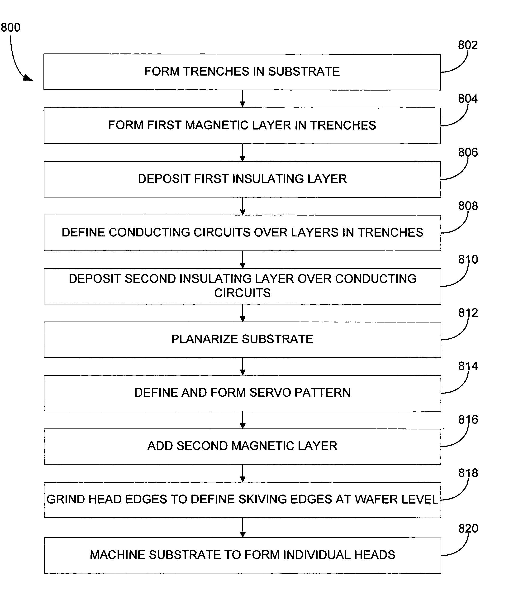
[0030]FIG. 4 illustrates a magnetic write head 400 for which the signal flux emerges from the plane 402 of the head, rather than from a cut and lapped edge. As shown, a first magnetically permeable layer 404 is positioned in a trench of a nonmagnetic substrate 406. An optional first insulating layer 408 is positioned on the first magnetically permeable layer. A current-carrying conducting circuit 410 for creating a magnetic flux is positioned on the first insulating layer 408 (or the first magnetic layer if no first insulating layer 408 is present). The conducting circuit 410 can be a single wire patterned below a data or servo write gap 411 pattern. The conducting circuit can also be a multi-turned...


PUM

PropertyMeasurementUnit
thickaaaaaaaaaa
magnetic fluxaaaaaaaaaa
conductingaaaaaaaaaa

Abstract

A magnetic write head and method for bulk fabrication of the same are provided. A trench is formed in a nonmagnetic substrate. A first magnetically permeable layer is deposited in the trench of the substrate. An optional first insulating layer is deposited in the trench. A conducting circuit is defined in the trench. The conducting circuit creates the magnetic flux. An optional second insulating layer is deposited in the trench. Writer gaps are patterned and then a second magnetic layer is added over the second insulating layer. The substrate is divided to form individual write heads.

Description

RELATED APPLICATIONS [0001] This application is a divisional of co-pending U.S. patent appl. Ser. No. 10 / 354,834, filed Jan. 29, 2003.FIELD OF THE INVENTION [0002] The present invention relates to magnetic write heads for writing to a magnetic storage media, and more particularly, this invention relates to flat profile write head design for writing magnetic transitions onto flexible magnetic storage media. One application is writing the patterns needed for timing-based servo, such as is used with the LTO (Linear Tape Open) standard. Another application is that for writing data in general. BACKGROUND OF THE INVENTION [0003] Servo control systems that maintain the position of a magnetic head relative to tracks in magnetic storage media are well known. European Patent Application EP 0 690 442 A2, published Jan. 3, 1995, entitled “Servo Control System”, Albrecht et al., describes a servo control system having a magnetic recording head for writing servo position code across the width of ...

Claims


Application Information

Patent Timeline
Patent Type & Authority Applications(United States)
IPC IPC(8): G11B5/008G11B5/187
CPCG11B5/00813G11B5/1871Y10T29/49048Y10T29/49052Y10T29/49798Y10T29/49046Y10T29/4903Y10T29/49021
Inventor BISKEBORN, ROBERT GLENNDOSCHER, MICHAEL J.EATON, JAMES HOWARD
Owner INT BUSINESS MASCH CORP
Learn More