Using constrained optimization in curve editing

a curve and curve technology, applied in computing, instruments, drawing from basic elements, etc., can solve the problems of inordinately large curve changes, inability to meet expectations, and difficulty in reshaping the curve in this manner, and achieve the effect of more design productivity

Inactive Publication Date: 2005-10-27
MICROSOFT TECH LICENSING LLC
View PDF5 Cites 32 Cited by
  • Summary
  • Abstract
  • Description
  • Claims
  • Application Information

AI Technical Summary

Benefits of technology

[0004] A curve is reshaped by determining new locations for its control points that minimize some measure of the change in the curve (typically, the “energy” of the change), while meeting the specified editing constraints. For example, a designer may indicate an editing constraint by selecting a point anywhere on a curve and moving it to a new location. In response, the unconstrained control points may be moved automatically and simultaneously to optimal new locations. The resulting change in the curve may be aesthetically pleasing and satisfy the editing constraints. This curve editing technique may allow designers to be more productive by providing predictable and intuitive results while manipulating curves directly.

Problems solved by technology

Because several control points may need to be moved by different amounts in different directions to achieve the desired result, it can be tedious to edit a shape in this manner.
Unfortunately, reality does not always meet expectations.
For instance, some applications that permit direct manipulation of open-ended curves display unpredictable results when the designer attempts to drag a point on the curve that is close to one of the curve endpoints.
Sometimes a small movement by the designer results in an inordinately large change in the curve.
In extreme cases, the edited curve may include unwanted loops, or a change may unexpectedly invert the curve.

Method used


Image

  • Using constrained optimization in curve editing
  • Using constrained optimization in curve editing
  • Using constrained optimization in curve editing

Examples


Embodiment Construction

Overview

[0011] A user of a vector drawing tool has several implicit expectations of a click and drag edit, namely:

[0012] The targeted point should follow the mouse pointer during the drag.

[0013] The edit should be local: points on the curve far from the edit point should not be affected.

[0014] The edit should be stable: small movements of the mouse should not result in large changes to the curve.

[0015] The edit should be intuitive in that the shape of the curve should only be distorted as much as necessary for it to meet the above requirements.

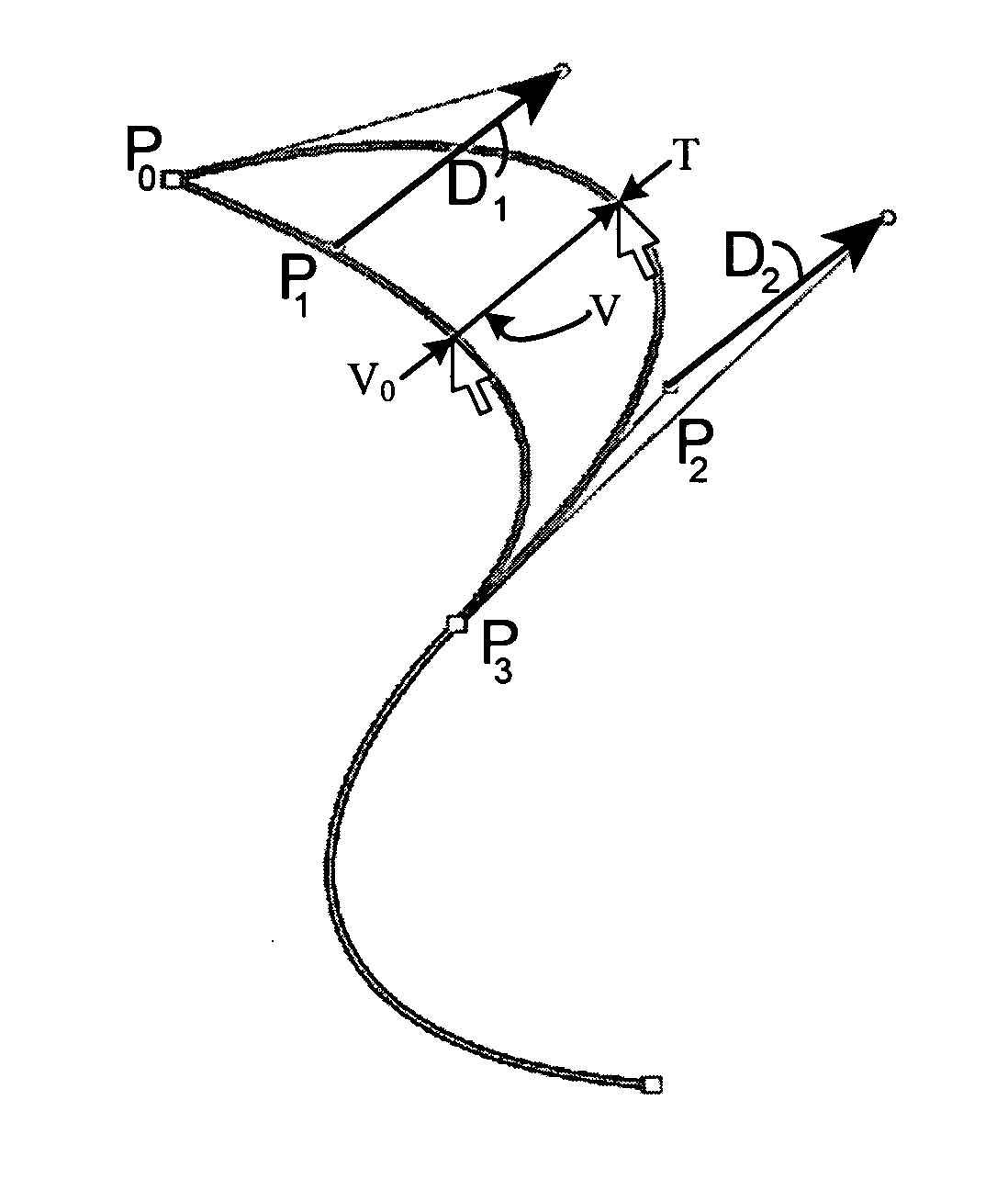
[0016] A curve frequently used as the underlying representation in vector drawing tools is the piecewise cubic Bézier spline. The invention described herein is independent of the underlying curve representation; however, because the piecewise cubic Bézier spline is one of the most commonly used representations, descriptions of the method will be given in terms of this representation. It will be understood that the method may be applied ...


PUM


Abstract

A curve may be reshaped by determining new locations for its control points that minimize some measure of the change in the curve (typically, the “energy” of the change), while meeting the specified editing constraints. For example, a designer or other user may indicate an editing constraint by selecting a point anywhere on a curve and moving it to a new location. In response, the unconstrained control points may be moved automatically and simultaneously to optimal new locations. The resulting change in the curve may be aesthetically pleasing and satisfy the editing constraints. This curve editing technique may allow designers to be more productive by providing predictable and intuitive results while enabling curves to be directly manipulated.

Description

FIELD OF THE INVENTION [0001] The invention relates to computing and in particular to reshaping a curve in computer graphics by minimizing an energy function subject to editing constraints. BACKGROUND OF THE INVENTION [0002] Graphic designers want tools that enable them to quickly and easily modify shapes. Within graphic design applications, these shapes are often modeled using curve representations that are defined by a sequence of control points, where the position of each control point has some influence on the shape of the curve. Examples of such shape representations include Bézier curves, B-splines, non-uniform rational B-splines (NURBS), and subdivision curves, among others. Graphic design applications typically allow the designer to edit a shape by moving one or more control points until the desired shape is achieved. Because several control points may need to be moved by different amounts in different directions to achieve the desired result, it can be tedious to edit a sha...

Claims


Application Information

Patent Timeline
Patent Type & Authority Applications(United States)
IPC IPC(8): G06T11/20
CPCG06T11/203
Inventor MOTTER, DORON B.KALLAY, MICHAEL
Owner MICROSOFT TECH LICENSING LLC
Why Eureka
Try Eureka