Cutter having shaped working surface with varying edge chamber

a technology of cutting edge chamber and working surface, which is applied in the direction of drill bits, earthwork drilling and mining, construction, etc., can solve the problems of cutter failure, cracking, spalling, chipping and partial fracturing, etc., and achieve the effect of reducing the adverse effects of sudden increase in loading

Active Publication Date: 2005-11-10
SMITH INT INC
View PDF74 Cites 120 Cited by
  • Summary
  • Abstract
  • Description
  • Claims
  • Application Information

AI Technical Summary

Benefits of technology

The present invention provides an ultra-hard cutter with a specially designed working surface that reduces negative impacts caused by changing conditions during drilling operations. This design features a chamfered shape that improves load bearing capacity and helps prevent damage to the drill bit from sudden increases in stress.

Problems solved by technology

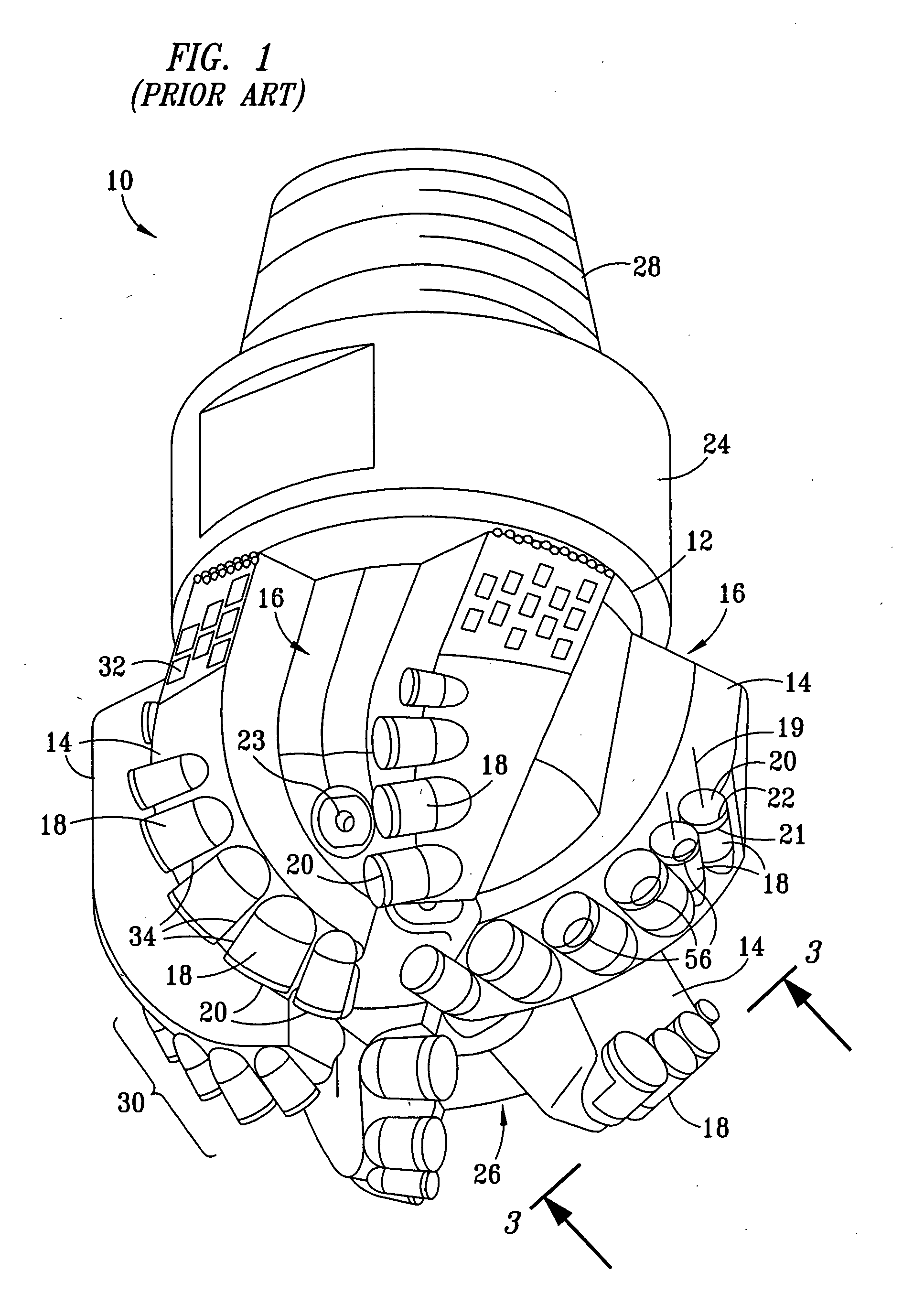
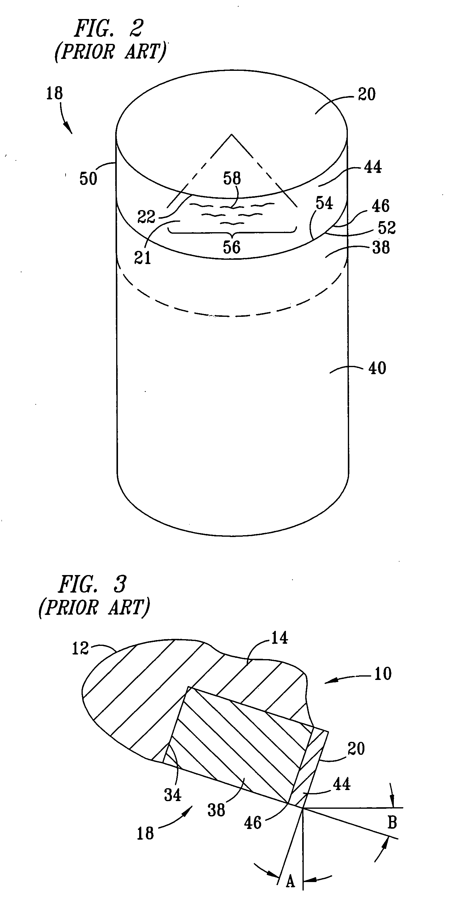
The technical problem addressed in this patent text relates to improving the performance of drill bit cutters in challenging environments where there is no ideal solution for every situation. Various factors like formation properties, change in direction of pressure, and unstable weather patterns contribute to damage and fatigue of the cutters. Existing solutions like applying larger angling or increasing the number of champers fail to adequately address these issues. Therefore, there is a desire for new cutters that can improve their ability to resist high levels of loading, maintain optimal cutting rates under various circumstances, and adapt to varying formations.

Method used


Image

  • Cutter having shaped working surface with varying edge chamber
  • Cutter having shaped working surface with varying edge chamber
  • Cutter having shaped working surface with varying edge chamber

Examples


Embodiment Construction

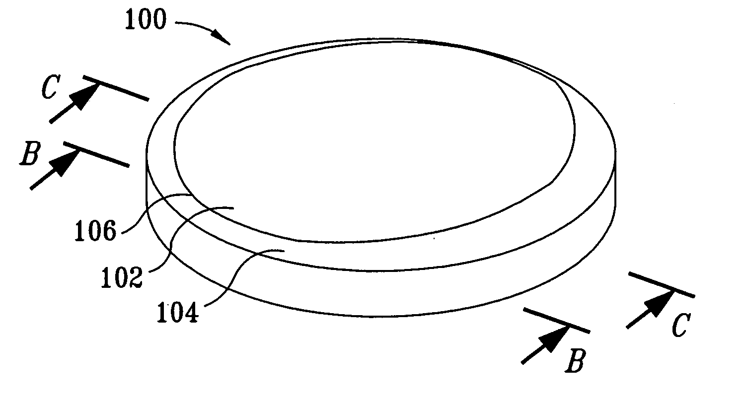
[0062] Embodiments of the present invention relate to cutters having shaped working surfaces with a varied geometry chamfer. By using such a structure, the present inventors have discovered that such cutters can better withstand high loading at the critical region imposed during drilling so as to have an enhanced operating life. According to certain aspects of the invention, cutters with shaped working surfaces with variable chamfer can cut efficiently at designed speed, penetration and loading conditions and can compensate for the amount of cutting load in changing formations. Such varied chamfer geometry has been found to variably increase the strength of the cutter edges in response to increased cutting depth, and according to certain aspects of the invention, to increase the strength of the cutter edges proportionally to the increased load associated with increased depth of cutting.

[0063]FIG. 6A shows an ultra hard top layer 100 for a cutter that has a shaped working surface 10...


PUM


Abstract

A cutter for a drill bit used for drilling wells in a geological formation includes an ultra hard working surface and a chamfer along an edge of the working surface, wherein the chamfer has a varied geometry along the edge. The average geometry of the chamfer varies with cutting depth. A depression in the shaped working surface is oriented with the varied chamfer and facilitates forming the varied chamfer. A non-planar interface has depressions oriented with depressions in the shaped working surface to provide support to loads on the working surface of the cutter when used.

Description


Claims


Application Information

Patent Timeline
Owner SMITH INT INC
Why Eureka
Try Eureka