
Paint roller tray

a paint roller and a technology for trays, which are applied in the direction of carpet cleaners, pliable tubular containers, cleaning machines, etc., can solve the problems of frequent interference of use of the paint brush on the paint roller tray, and achieve the effect of facilitating the pouring of pain

Inactive Publication Date: 2005-11-17
STANLEY WORKS THE
View PDF28 Cites 39 Cited by
  • Summary
  • Abstract
  • Description
  • Claims
  • Application Information

AI Technical Summary

Benefits of technology

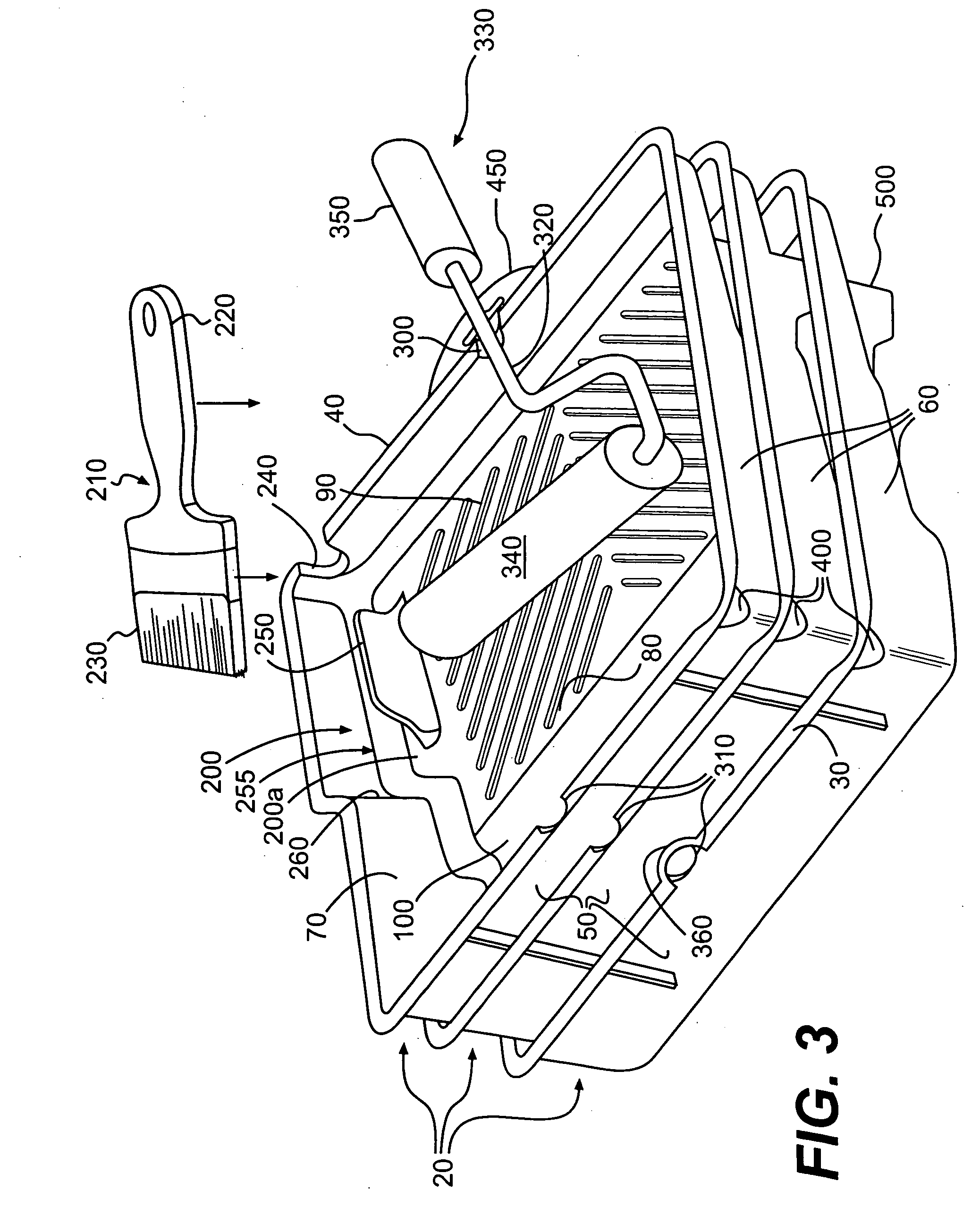
[0012] Another aspect of one or more embodiments of the present invention provides a paint roller tray that includes a useful combination of one or more of the following features: a cover, a hanging fixture for hanging the tray when not in use, front and rear support notches for a paint roller, a paint brush support notch that does not interfere with use of the tray by a paint roller, a bulge in the cover that is shaped so that a paint brush and a paint roller may be entirely enclosed within the tray between the cover and a tray body, a pour spout that facilitates the easy pouring of paint out of the tray, and slip-resisting surface features disposed on an underside of the tray.

Problems solved by technology

Unfortunately, as would be appreciated by one of ordinary skill in the art, resting the paint brush on the paint roller tray frequently interferes with the use of the paint roller tray by the paint roller because the paint brush disadvantageously occupies the roll-out platform used by the paint roller.

Method used


Image

  • Paint roller tray
  • Paint roller tray
  • Paint roller tray

Examples


Embodiment Construction

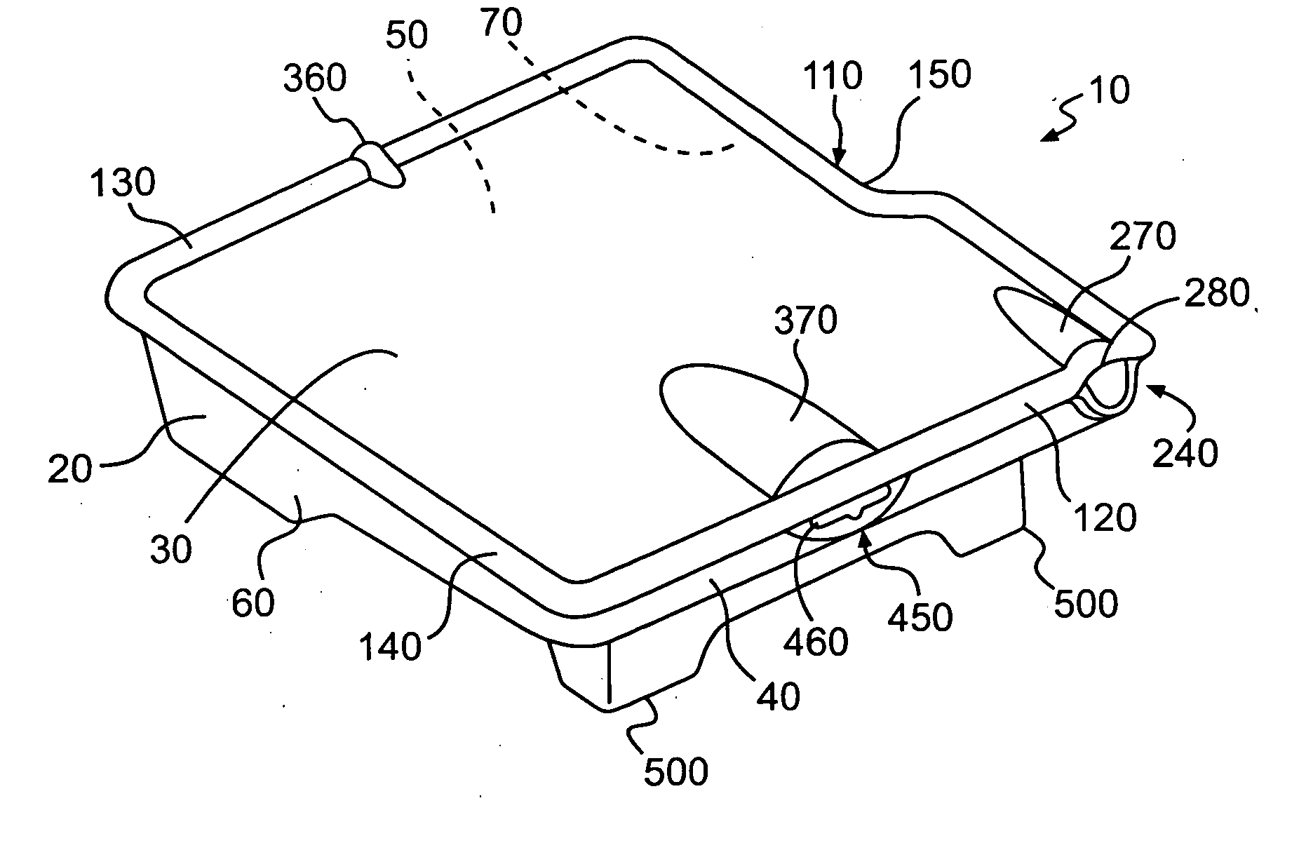
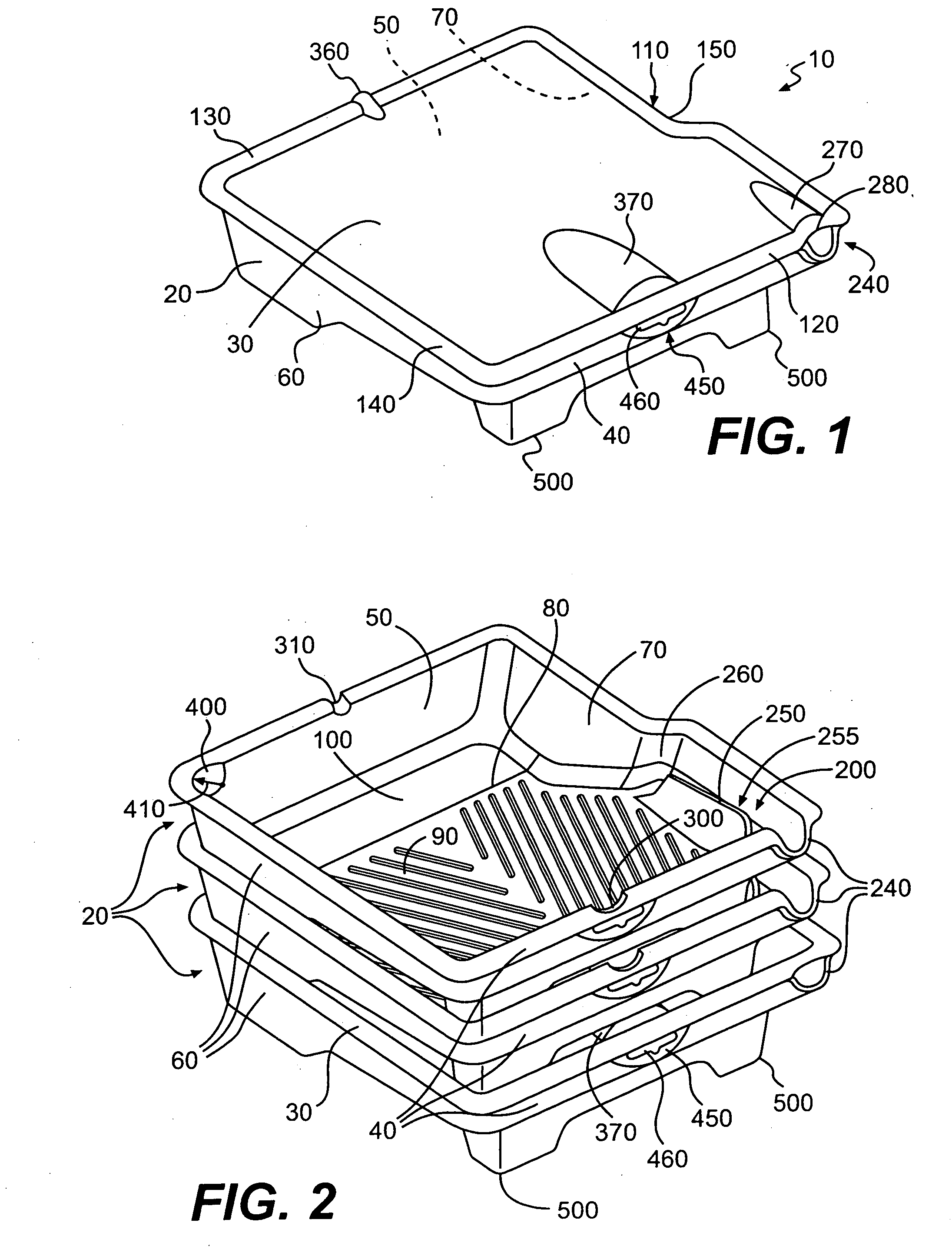
[0036]FIG. 1 illustrates a paint roller tray 10 according to an embodiment of the present invention. The paint roller tray 10 includes a tray body 20 and a selectively removable cover 30. The tray body 20 and cover 30 are preferably each formed of molded plastic, but may alternatively comprise any other suitable material such as stamped metal, cast metal, etc. The cover 30 preferably comprises a clear plastic so that any paint, brushes, or other objects in the tray 10 can be seen through the cover 30.

[0037] As shown in FIGS. 2 and 3, the tray body 20 has opposing front and back walls 40, 50, and opposing left and right side walls 60, 70 that join with the front and back walls 40, 50 to form an open topped space, which generally forms a rectangular shape. The tray body 20 also includes a bottom 80 that joins to lower portions of the walls 40, 50, 60, 70. The bottom 80 defines a sloped rollout platform 90. The bottom 80, back wall 50, and side walls 60, 70 define a paint well 100. Th...


PUM

PropertyMeasurementUnit
heightaaaaaaaaaa
widthaaaaaaaaaa
radiusaaaaaaaaaa

Abstract

A paint roller tray is provided with a removable cover. The paint roller tray includes a paint brush support formed in a front side of the tray, front and back paint roller support notches, a pour spout, a hanging fixture, and support legs. The cover includes paint roller and paint brush accommodating bulges that allow the cover to be mounted to the tray while a paint roller and a paint brush are disposed wholly or partially between the tray and cover.

Description

BACKGROUND OF THE INVENTION [0001] 1. Field of the Invention [0002] This invention relates to paint roller trays with covers, and specifically relates to paint roller trays that are adapted to support paint rollers and paint brushes. [0003] 2. Description of Related Art [0004] Various conventional paint roller trays include covers that are designed to prevent paint therein from quickly drying. U.S. Pat. No. 5,645,164 discloses one such covered paint roller tray. As shown in FIG. 3 thereof, a paint roller and a paint brush may be supported on the paint roller tray. Unfortunately, as would be appreciated by one of ordinary skill in the art, resting the paint brush on the paint roller tray frequently interferes with the use of the paint roller tray by the paint roller because the paint brush disadvantageously occupies the roll-out platform used by the paint roller. [0005] U.S. Pat. No. 6,622,884 discloses a conventional paint roller tray that includes a pour spout to aid in pouring pai...

Claims


Application Information

Patent Timeline
Patent Type & Authority Applications(United States)
IPC IPC(8): B44D3/12
CPCB44D3/126
Inventor CUMMING, ALISDAIRROWLAY, STEPHENRANIERI, ERIC
Owner STANLEY WORKS THE
Learn More