

Fire demonstration tool and method for using thereof
- Summary
- Abstract
- Description
- Claims
- Application Information
AI Technical Summary
Benefits of technology
Problems solved by technology
Method used
Image

Examples
Embodiment Construction
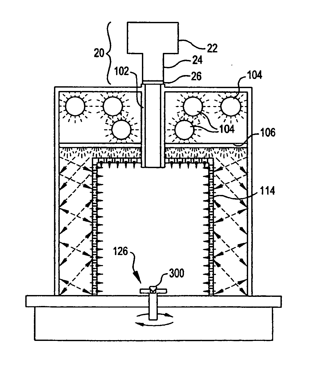
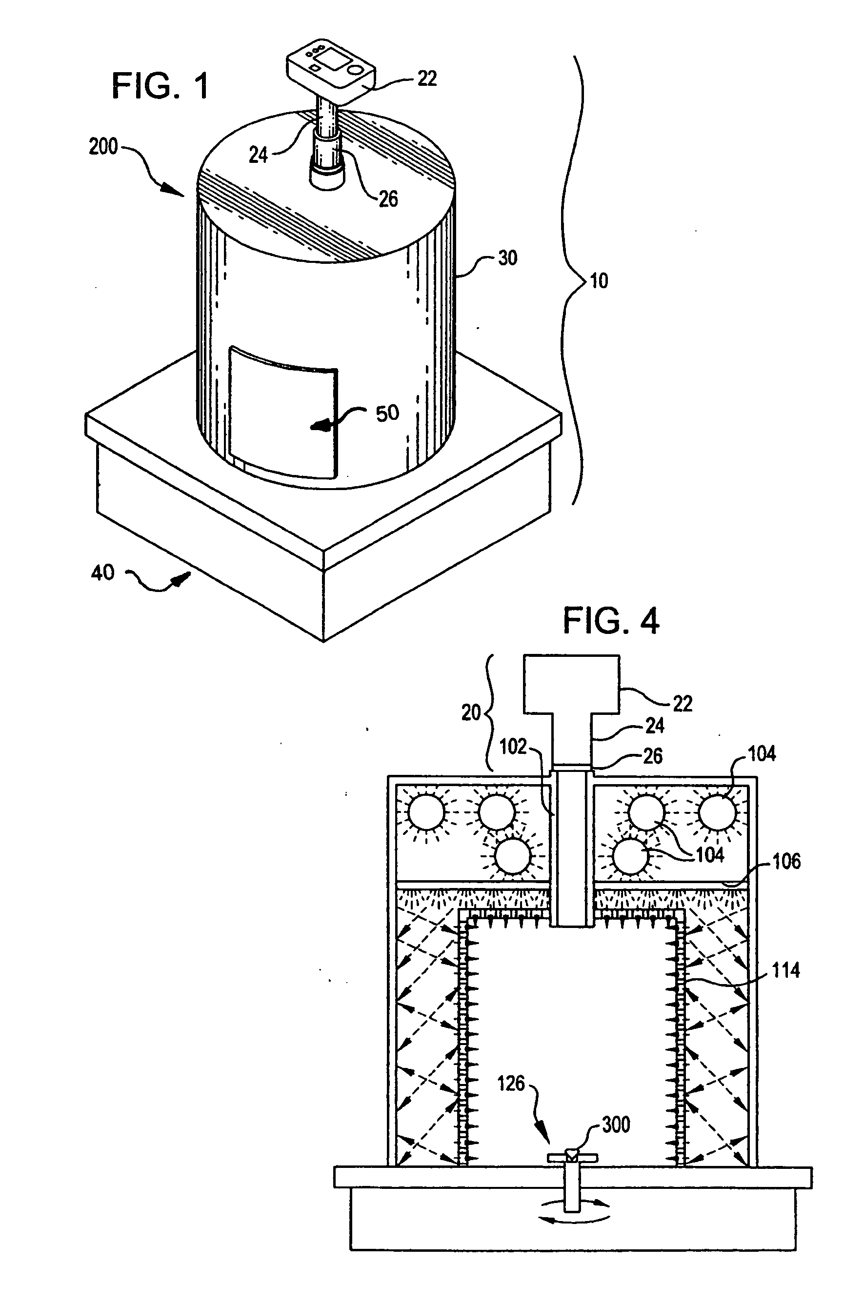
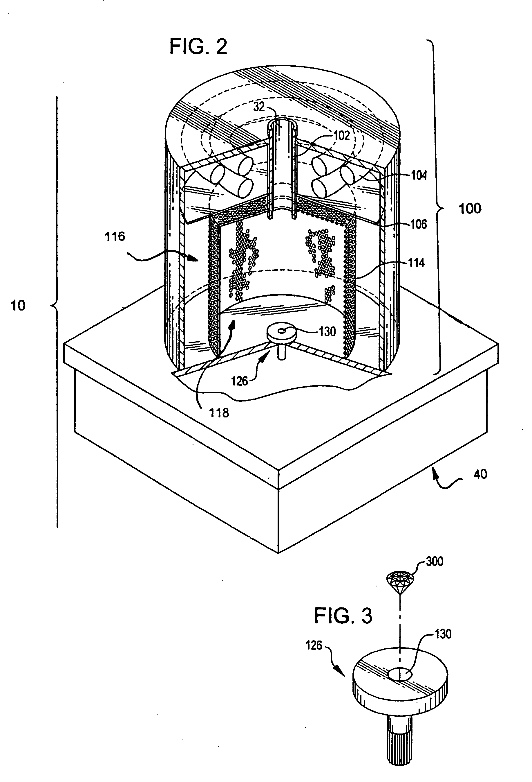
[0027] The present invention is directed to a device 200 for imaging a gem 300, and more specifically, a device 200 capable of imaging the fire of a gem 300 and thereby enabling its qualitative assessment. The gem imaging device 200 of the present invention allows a user to image the fire of a gem 300 in a qualitatively repeatable manner.
[0028] For purposes of this detailed description, imaging a gem 300 in a qualitatively repeatable manner means that, while rotation or repositioning of the gem 300 may change the color of an individual fact of the gem 300, the overall quality of the characterization of the gem 300 is relatively unchanged.
[0029] Further, the term “imaging,” as used throughout this detailed description, means viewing and capturing the image of a gem 300 by means of an eye, a camera, a video camera, telescope, or any other device capable of viewing, capturing, recording, or photographing a gem 300.
[0030] The gem imaging device 200, as shown in FIGS. 1-4, includes an...
PUM
 Abstract
Description
Claims
Application Information