Golf club head

Inactive Publication Date: 2005-11-24
SUMITOMO RUBBER IND LTD
View PDF3 Cites 80 Cited by
  • Summary
  • Abstract
  • Description
  • Claims
  • Application Information

AI Technical Summary

Benefits of technology

[0003] An object of the present invention is therefore, to provide a golf club head having a crown portion which

Problems solved by technology

In other words, it is difficult to decrease an energy loss at impact close to zero.
As a result, there is a limit to the improvement in the rebound performance of such head.
Further, as the vibrations of the crown portion are quic

Method used


Image

  • Golf club head
  • Golf club head
  • Golf club head

Examples


Example

[0019] Embodiments of the present invention will now be described in detail in conjunction with the accompanying drawings.

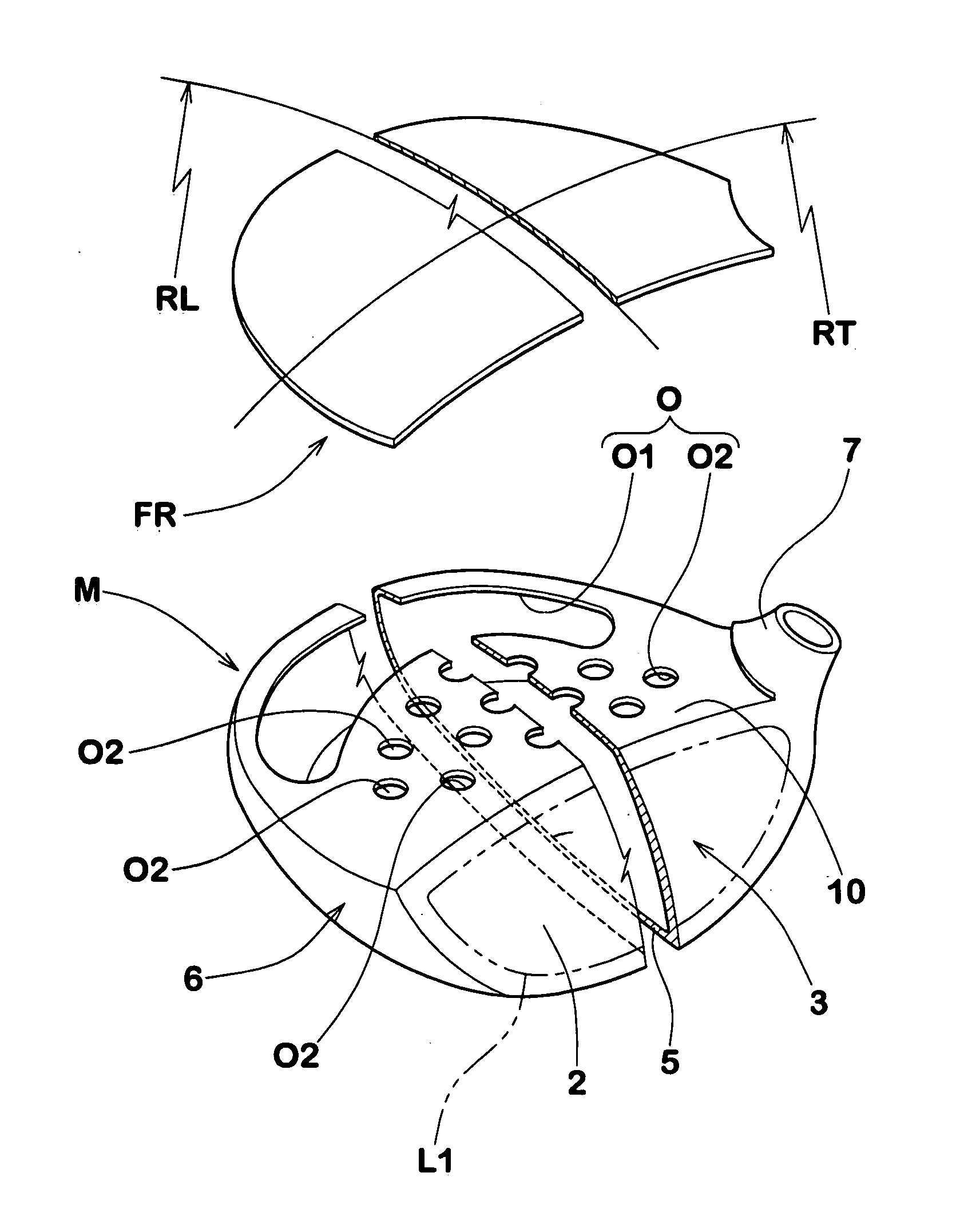
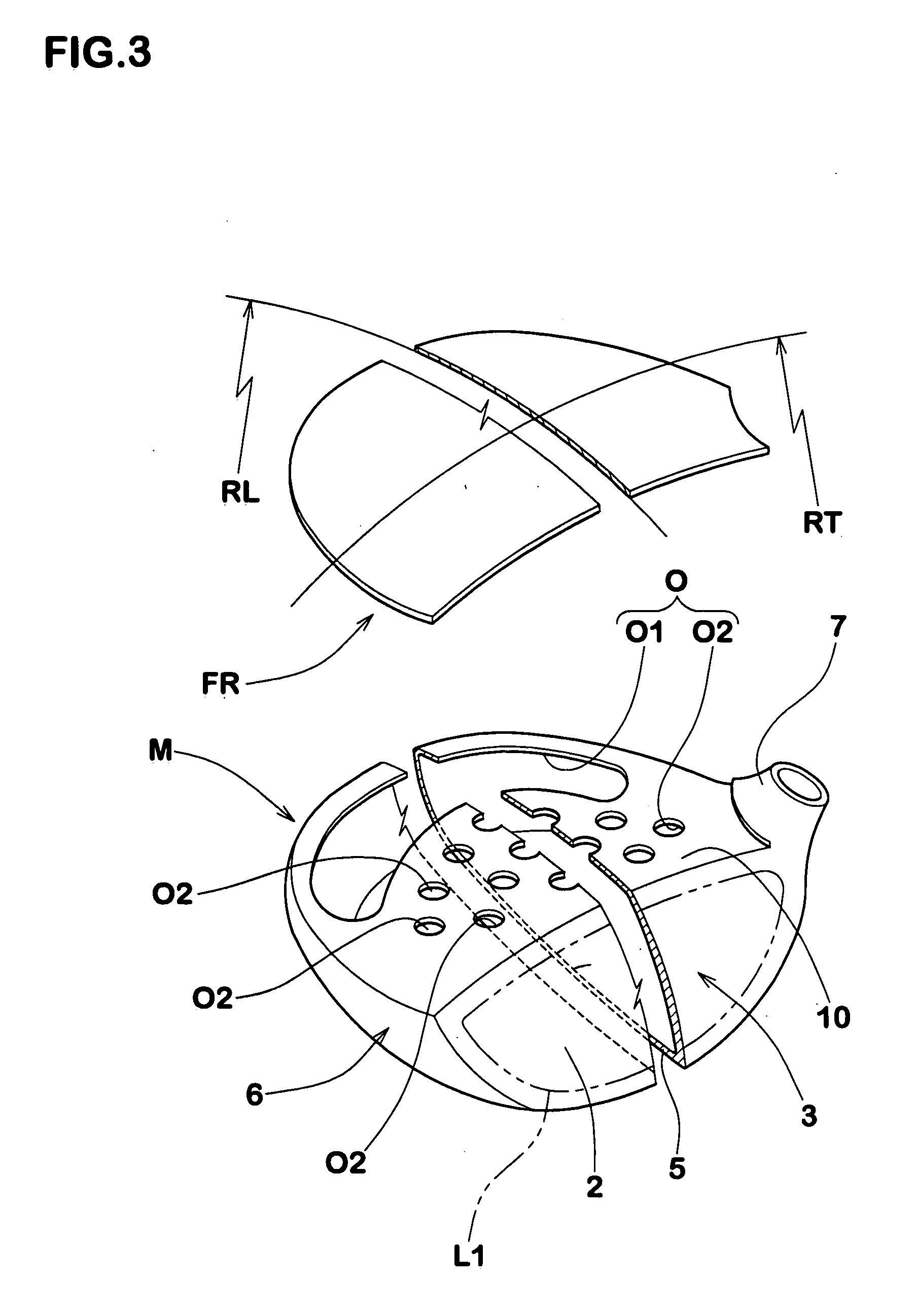
[0020] In the drawings, club head 1 according to the present invention is a wood-type hollow head such as driver (#1) and fairway wood.

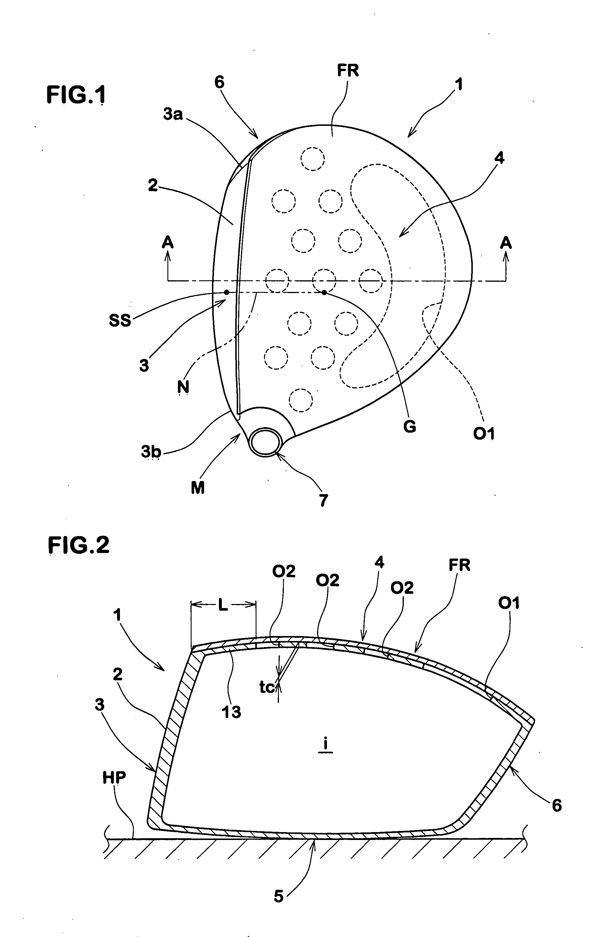
[0021] The head 1 comprises a face portion 3 whose front face defines a club face 2 for striking a ball, a crown portion 4 defining a top face of the clubhead and intersecting the club face 2 at the upper edge thereof, a sole portion 5 defining a bottom face of the clubhead or sole and intersecting the club face 2 at the lower edge thereof, a side portion 6 between the crown portion 4 and sole portion 5 which extends from a toe-side edge to a heel-side edge of the club face 2 through the back face of the club head, and a neck portion 7 to be attached to an end of a club shaft (not shown), whereby a closed cavity (i) is formed.

[0022] The volume of the head is preferably set in the range of not less than 300 cc, more preferably m...


PUM


Abstract

A golf club head comprises a main body and a crown cover disposed in a crown portion of the head, wherein the main body comprises a crown base made of a metal material and provided with a plurality of openings gradually decreasing in the opening area from the backside to the foreside of the head, and the crown cover is made of a material such as FRP whose specific gravity is lower than the metal material, and disposed on the crown base so as to cover the openings.

Description

BACKGROUND OF THE INVENTION [0001] The present invention relates to a golf club head, more particularly to a structure of the crown portion being capable of achieving a low center of gravity and a high restitution coefficient. [0002] In the Japanese patent application publication Nos.2003-205055 and 2003-250935, as shown in FIG. 14 as “Ref.2”, a golf club head comprising a main body whose top is opened as illustrated in dotted line, and a crown plate made of a fiber reinforced resin closing the top opening, has been proposed. As the almost entirety of the crown portion of the head is made of the fiber reinforced resin, the kinetic energy which the head receives from a golf ball at impact is consumed in the fiber reinforced resin in the crown portion. In other words, it is difficult to decrease an energy loss at impact close to zero. As a result, there is a limit to the improvement in the rebound performance of such head. Further, as the vibrations of the crown portion are quickly da...

Claims


Application Information

Patent Timeline
IPC IPC(8): A63B53/04A63B102/32
CPCA63B53/0466A63B2209/023A63B2053/042A63B2053/0408A63B2053/0437A63B2209/00A63B53/042A63B53/0408A63B53/0437
Inventor YAMAMOTO, AKIO
Owner SUMITOMO RUBBER IND LTD
Why Eureka
Try Eureka