Mobile field scorching apparatus

Inactive Publication Date: 2005-12-01
CARROLL MICHAEL E +2
View PDF26 Cites 7 Cited by
  • Summary
  • Abstract
  • Description
  • Claims
  • Application Information

AI Technical Summary

Problems solved by technology

A problem associated with this method of scalping is that once the grass is cut, it leaves a residue on the soil that tends to blow around and create environmental issues.
However, the grass must be hauled away at additional cost.
Also, not only sweepers cannot pick up all the grass, thi

Method used


Image

  • Mobile field scorching apparatus
  • Mobile field scorching apparatus
  • Mobile field scorching apparatus

Examples


Embodiment Construction

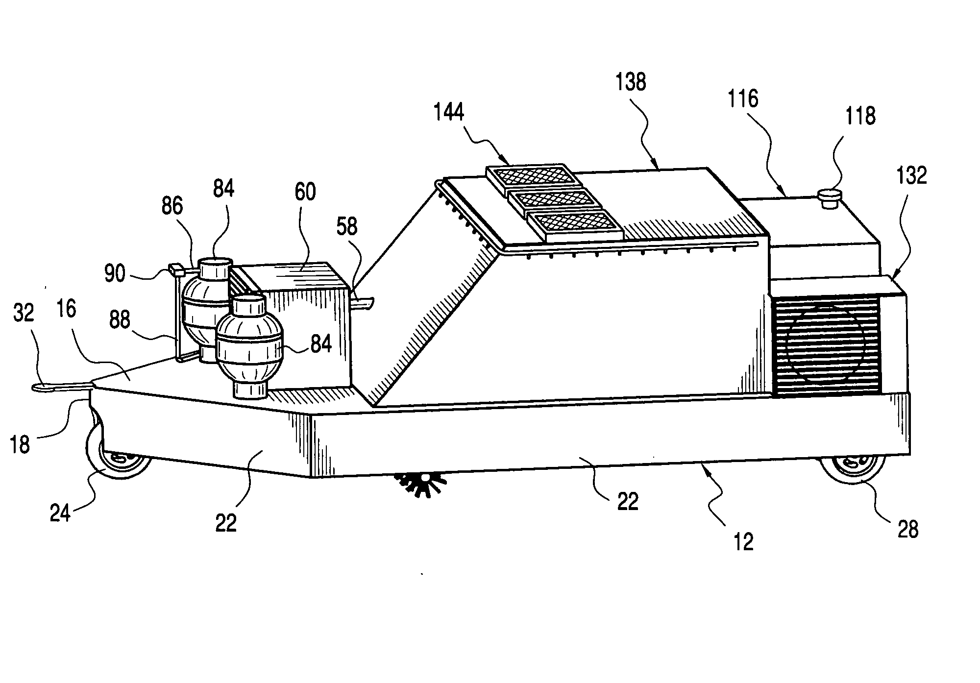
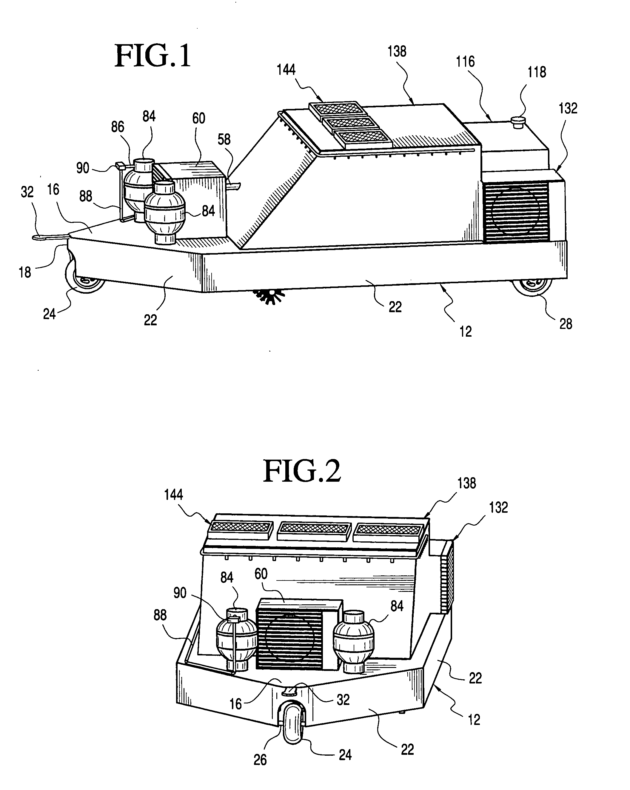
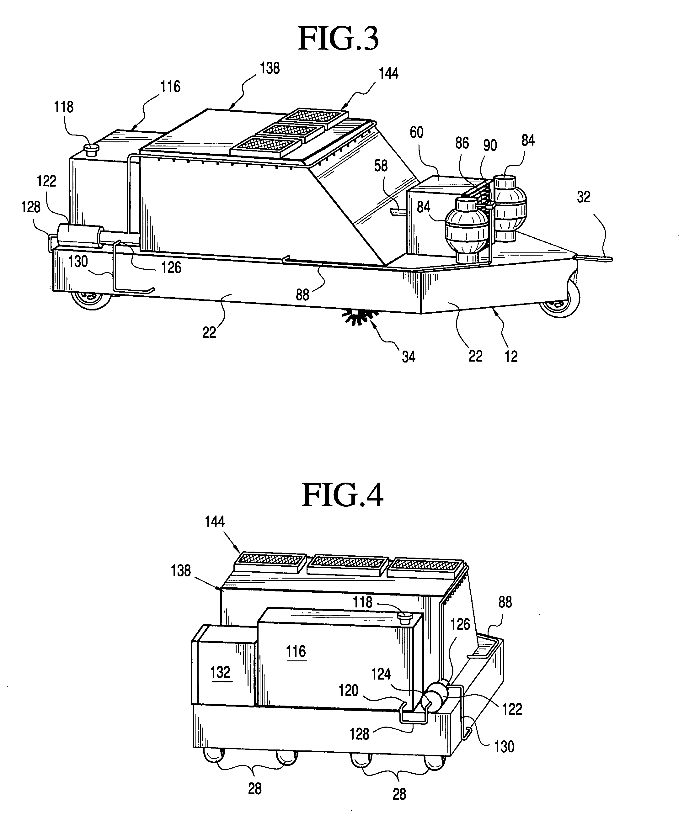
[0019] For the purpose of promoting and understanding of the principles of the invention, reference will now be made to the preferred embodiment illustrated in the drawings. Referring now to the drawings, and more specifically FIGS. 1 through 6, wherein the showings are for the purpose of illustrating the preferred embodiment of the invention only and not for the purpose of limiting the same, a mobile field scorching apparatus 10 comprises a main body 12 disposed on a chassis or support frame 14, wherein the main body 12 includes an upper support surface 16, a front end 18, a rear end 20, and a plurality of side panels 22 extending downwardly from the periphery of the upper surface 16 to bound an opening on an underside of the mobile field scorching apparatus 10.

[0020] The mobile field scorching apparatus 10 is movably supported on the ground by a front wheel 24 rotatably mounted on a front wheel axle 26 and a plurality of rear wheels 28 rotatably mounted on a rear wheel axle 30. T...


PUM


Abstract

The present invention provides a mobile field scorching apparatus having a chassis, a plurality of wheels rotatably supporting the chassis on the ground, a main body placed over the chassis, a brush bar rotatably attached to the chassis for loosening the thatch on a grass area, a flame blower operably attached to the chassis and positioned rear the brush bar for scorching the loosened grass thatch, and a water discharge apparatus operably attached to the chassis rear the flame blower for wetting down and curtaining the scorched grass.

Description

TECHNICAL FIELD [0001] The present invention is related to field scorching apparatus, and more specifically, to a mobile field scorching apparatus for loosening and scorching grass thatch, or scorching weeds, and subsequently wetting down the scorched grass to create fertilizer. BACKGROUND OF THE INVENTION [0002] The grass in golf courses or residential areas is scalped during the fall season. Scalping requires cutting the grass very short and then reseeding it with winter rye. A problem associated with this method of scalping is that once the grass is cut, it leaves a residue on the soil that tends to blow around and create environmental issues. To address this problem, it is a common practice to pick up the cut grass using sweepers. However, the grass must be hauled away at additional cost. Also, not only sweepers cannot pick up all the grass, this process creates a lot of dust and air pollution. [0003] Furthermore, to prevent fire, there is a need to control the growth of grass a...

Claims


Application Information

Patent Timeline
IPC IPC(8): A01B45/00A01D34/43A01D34/54A01D34/62A01M15/00A01M21/04
CPCA01M21/04A01M15/00
Inventor CARROLL, MICHAEL E.WHITFIELD, HEULAN D.CLARK, RICHARD C.
Owner CARROLL MICHAEL E
Why Eureka
Try Eureka