Push slide switch

a push-pull switch and slide-type technology, applied in the direction of electric switches, snap-action arrangements, electrical equipment, etc., can solve the problem that the operator cannot recogniz

Inactive Publication Date: 2005-12-01
SMK CORP
View PDF7 Cites 2 Cited by
  • Summary
  • Abstract
  • Description
  • Claims
  • Application Information

AI Technical Summary

Benefits of technology

[0008] In view of the above problems, an object of the invention is to provide a slide switch which can cause an operator to recognize that terminals have been electrically connected more effectively than in case that a knob is abutted against an abutting part.

Problems solved by technology

Therefore, the operator cannot recognize, by the change of the force necessary for operation of the knob, that the terminals have been electrically connected.

Method used


Image

  • Push slide switch
  • Push slide switch
  • Push slide switch

Examples


Embodiment Construction

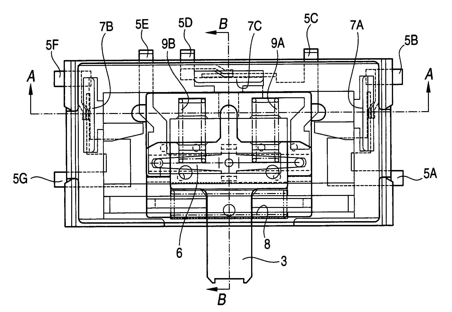
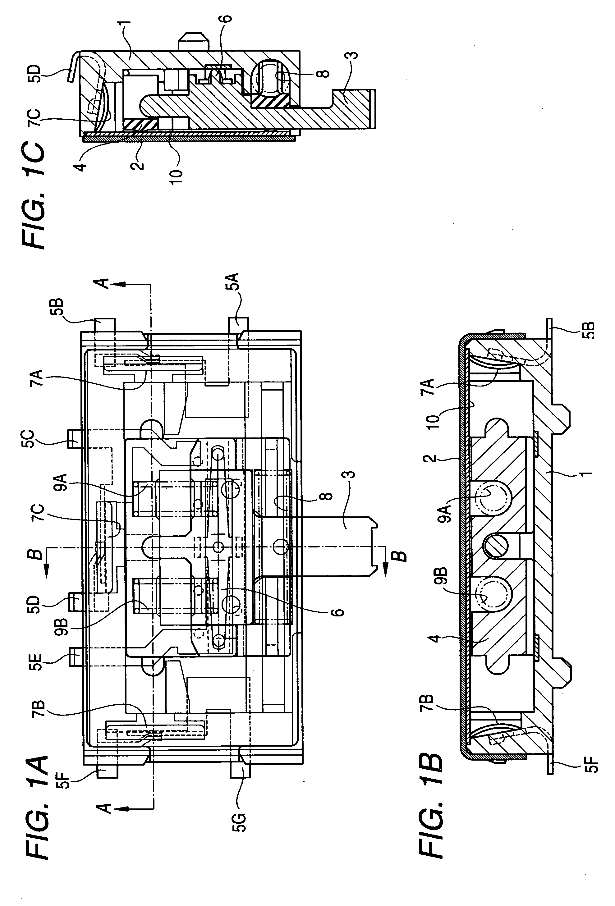
[0077]FIGS. 1A to 1C are diagrams showing a first embodiment of a push slide switch of the invention. Specifically, FIG. 1A is a plan view of the push slide switch in the first embodiment, FIG. 1B is a sectional view taken along a line A-A of FIG. 1A, and FIG. 1C is a sectional view taken along a line B-B of FIG. 1A.

[0078] In FIG. 1, reference numeral 1 is a housing of the push slide switch. This housing 1 is formed by molding, for example, resin material. Reference numeral 2 is a cover for covering the inside of the housing 1. This cover 2 is formed of, for example, metal material. Reference numeral 3 is a knob constituted so that an operator of the push slide switch can slide the knob in left and right directions of FIG. 1A, and can push the knob upward. This knob 3 is formed of, for example, resin material. Reference numeral 4 is a slider which is constituted so that it can slide integrally with the knob 3 in the left and right directions of FIG. 1A. This slider 4 is formed of, ...


PUM


Abstract

For a push slide switch in which as a knob is slid, terminals and are electrically connected, click springs and are provided, which have a characteristic that as displacement level is increased, stress increases, and as the displacement level is more increased, the stress decreases sharply. The click springs and are arranged so that force necessary for operation of the knob decreases sharply when the terminals are electrically connected.

Description

BACKGROUND OF THE INVENTION [0001] The present invention relates to a slide switch in which as a knob is slid, terminals are connected electrically, and particularly to a slide switch which causes an operator to recognize that the terminals are electrically connected more effectively than in a case that a knob is abutted against an abutting part. [0002] Further, the invention relates to a slide switch and a push slide switch, in which as a knob is slid, terminals are connected electrically, and particularly to a slide switch and a push slide switch, in which connection states of more terminals than terminals in the related case can be switched by a slide operation of the knob. [0003] Heretofore, a push slide switch in which as a knob is slid, terminals are connected electrically, has been known. An example of this type of push slide switch has been disclosed in JP-A-2001-229781. [0004] A push slide switch described in JP-A-2001-229781 is so constituted that: as a knob is slid, a coi...

Claims


Application Information

Patent Timeline
Patent Type & Authority Applications(United States)
IPC IPC(8): H01H5/20H01H15/00H01H15/06H01H15/18H01H25/00
CPCH01H25/002H01H15/18
Inventor MAEHARA, MASATAKA
Owner SMK CORP
Why Eureka
Try Eureka