Electrical connection device

a technology of electrical connection and connector, which is applied in the direction of connection, coupling device connection, electrical apparatus, etc., can solve the problems of affecting the working efficiency of the connection device, and having to be performed manually

Inactive Publication Date: 2018-12-13
AUTONETWORKS TECH LTD +2
View PDF1 Cites 0 Cited by
  • Summary
  • Abstract
  • Description
  • Claims
  • Application Information

AI Technical Summary

Benefits of technology

[0006]The invention is directed to an electrical connection device for establishing electrical connection between a first wiring material wired in a first member and a second wiring, material wired in a second member to be coupled to the first member in a coupling direction along a predetermined rotation center axis and to be relatively rotatable about the rotation center axis. The electrical connection device includes a first connector to be connected to the first wiring material and fixed to the first member. The electrical connection device also includes a second connector to be connected to the second wiring material and mounted on the first member and configured to form the electrical connection by being connected to the first connector in a specific connecting direction. A connector holding member is linked to the second member and is configured to hold the second connector at a position where the first and second connectors are capable of facing each other in the connecting direction with the first and second members coupled. The connector holding member holds the second connector in such a manner as to allow the second connector to be separated from the connector holding member in the connecting direction upon application of an external force to the second connector in the connecting direction. The electrical connection device further includes a connecting operating member to be held in a holding connector selected from the first and second connectors and is relatively movable in an operating direction intersecting the connecting direction. The connecting operating member includes a connector operating portion that is configured to connect the first and second connectors to each other by pulling an operated connector on a side opposite to the holding connector toward the holding connector along the connecting direction. The connector operating portion further is configured to separate the second connector from the connector holding member in the connecting direction by being relatively moved in the operating direction with respect to the holding connector in a state where the first and second members are coupled and the first and second connectors are facing each other in the connecting direction.

Problems solved by technology

Such operations of separating and connecting connectors are both cumbersome and have to be performed manually.
This impedes an improvement of working efficiency.

Method used


Image

  • Electrical connection device
  • Electrical connection device
  • Electrical connection device

Examples


Embodiment Construction

[0017]A preferred embodiment of the present invention is described with reference to the drawings.

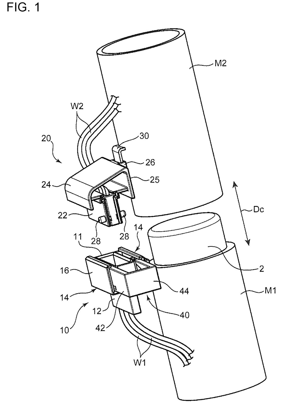
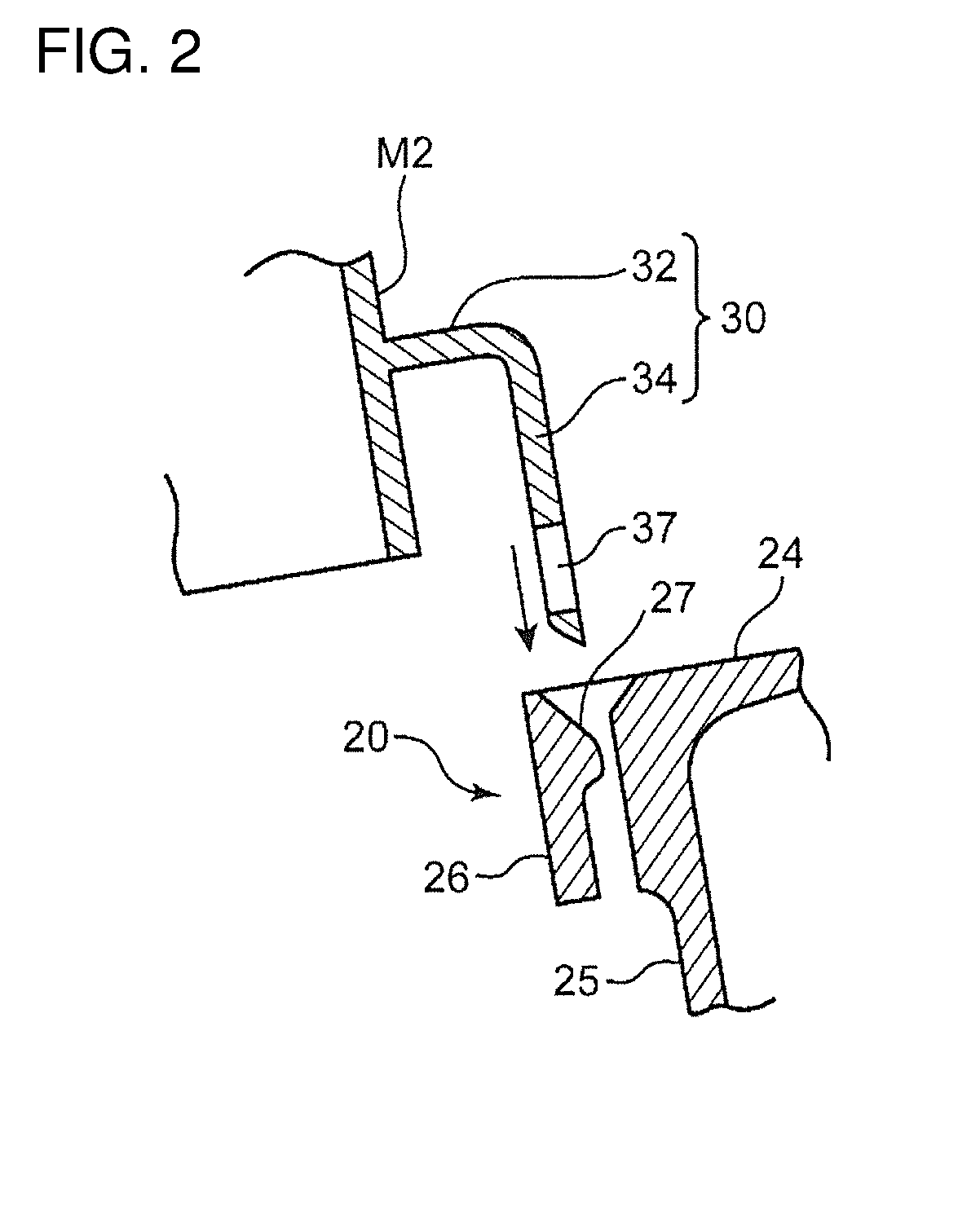
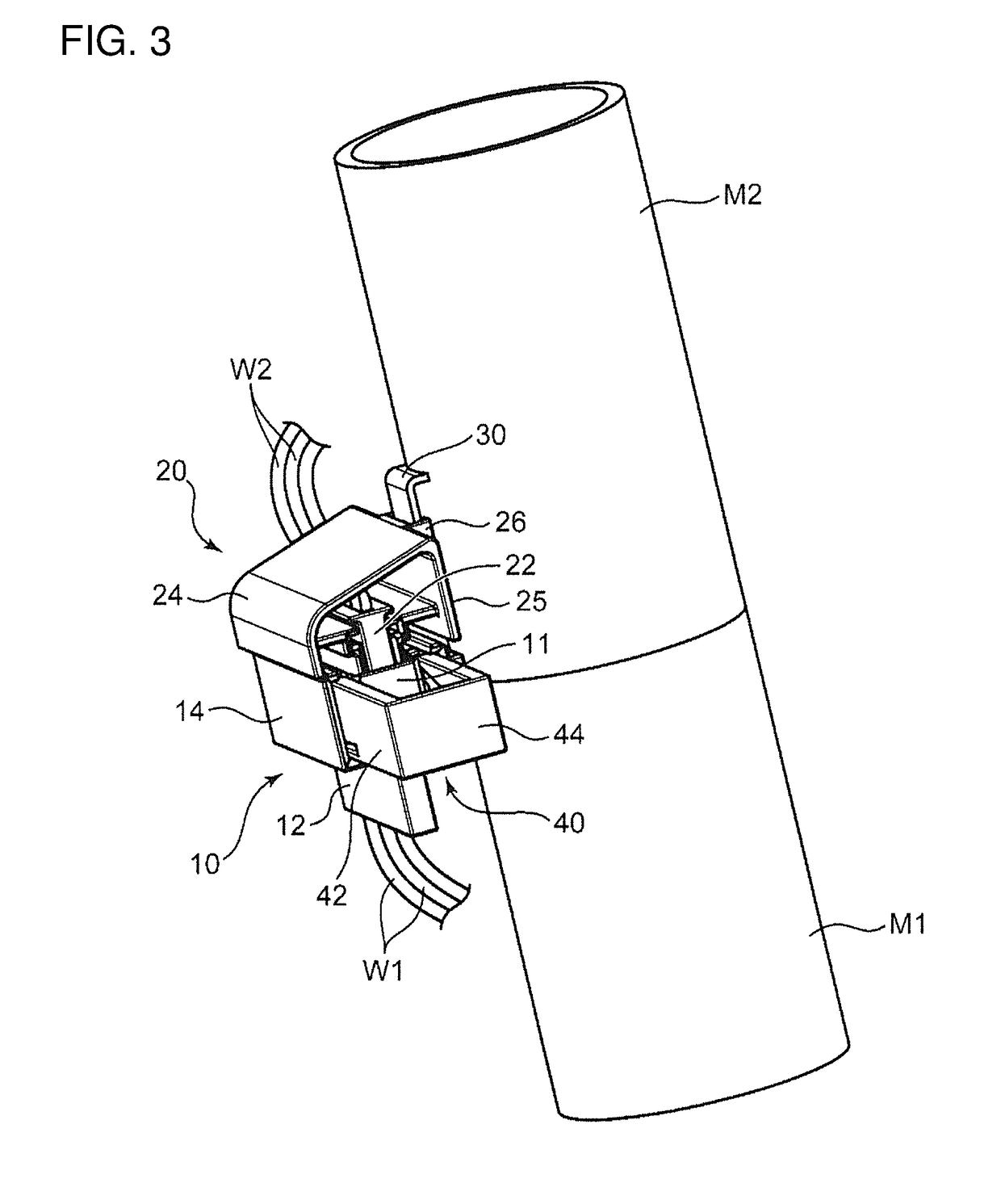
[0018]An electrical connection device according to this embodiment is for electrically connecting first wiring materials W1 wired in a first member M1 and second wiring materials W2 wired in a second member M2 that is to be coupled to the first member M1 to be relatively rotatable within a predetermined range. The electrical connection device includes a first connector 10, a second connector 20, a connector holding member 30 and a connecting operating member 40.

[0019]In this embodiment, the first member M1 is in the form of a cylinder or hollow cylinder extending in a vertical direction, and an upper end part thereof constitutes a fit-in portion 2 having a cylindrical outer peripheral surface with a diameter smaller than other parts. The second member M2 is in the form of a cylinder or hollow cylinder having a lower end into which the fit-in portion 2 is fittable. By fitting the fit-in ...


PUM


Abstract

An electrical connection device includes a first connector (10) to be connected to first wiring materials (W1) in a first member (M1) and fixed to the first member (M1), and a second connector (20) to be connected to second wiring materials (W2) in a second member (M2) and mounted on the second member (M2). A connector holding member (30) is linked to the second member (M2) and is configured to hold the second connector (20) releasably. A connecting operating member (40) is held in the first connector (10) or the second connector (20). The connecting operating member (40) connects the first and second connectors (10, 20) in a connecting direction and separates the second connector (20) from the connector holding member (30) by being operated in an operating direction intersecting the connecting direction in a state where the first and second connectors (10, 20) face each other.

Description

BACKGROUNDField of the Invention[0001]The invention relates to an electrical connection device for electrically connecting members coupled to each other to be relatively rotatable.Description of the Related Art[0002]Devices provided with connectors that are connectable to each other are used widely for electrically connecting circuits. Each connector includes a connector terminal to be connected to a predetermined circuit via a wire or the like and a connector housing for holding the connector terminal. The circuits connected to the respective connectors are connected electrically by connecting the connector terminals of the respective connectors.[0003]Each connector is used by being mounted at a suitable location of a vehicle or the like via a suitable mounting member. For example, Japanese Unexamined Patent Publication No. 2005-190806 that connectors of an electrical connection device are mounted on a vehicle body via fixing brackets.[0004]Members on which the connectors are mount...

Claims


Application Information

Patent Timeline
Patent Type & Authority Applications(United States)
IPC IPC(8): H01R13/631
CPCH01R13/631H01R13/62911H01R13/639
Inventor MIYAMURA, TETSUYATABATA, MASAAKIOMORI, YASUO
Owner AUTONETWORKS TECH LTD
Why Eureka
Try Eureka