Rotation-controlled lamp for controlling actuation and de-actuation of the lamp

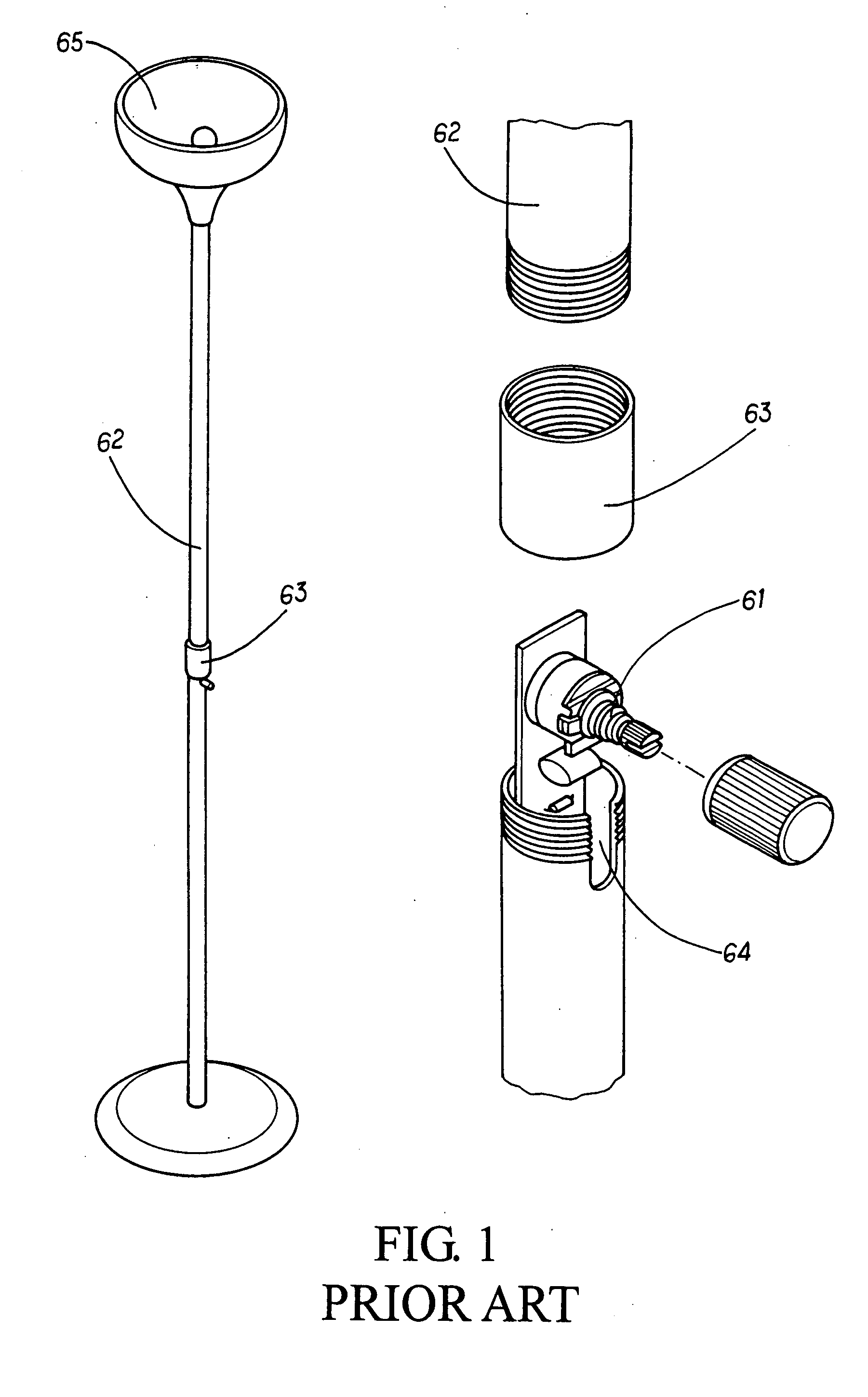
a technology of rotating control and lamp, which is applied in the direction of fixed installation, lighting and heating equipment, and support devices for lighting, etc., can solve the problems of time and labor waste, difficult for children or some disablers, and the small button of the light adjuster, etc., and achieves a beautiful outlook and convenient and convenient installation.

Inactive Publication Date: 2005-12-08
CHEN MEIRIC
View PDF9 Cites 1 Cited by
  • Summary
  • Abstract
  • Description
  • Claims
  • Application Information

AI Technical Summary

Benefits of technology

[0003] Accordingly, the primary object of the present invention is to provide a rotation-controlled device for controlling actuation and de-actuation of the lamp, wherein the actuation of the lamp can be controlled by operating an upper cover so that user can operate it easily and conveniently. Moreover, the present invention has a beautiful outlook.

Problems solved by technology

Furthermore, the button of the light adjuster is small.
However, this is difficult to the children or some disablers.
Moreover, the installation and positioning of the light adjuster 61 is time and labor wasted.

Method used


Image

  • Rotation-controlled lamp for controlling actuation and de-actuation of the lamp
  • Rotation-controlled lamp for controlling actuation and de-actuation of the lamp
  • Rotation-controlled lamp for controlling actuation and de-actuation of the lamp

Examples


Embodiment Construction

[0014] In order that those skilled in the art can further understand the present invention, a description will be described in the following in details. However, these descriptions and the appended drawings are only used to cause those skilled in the art to understand the objects, features, and characteristics of the present invention, but not to be used to confine the scope and spirit of the present invention defined in the appended claims.

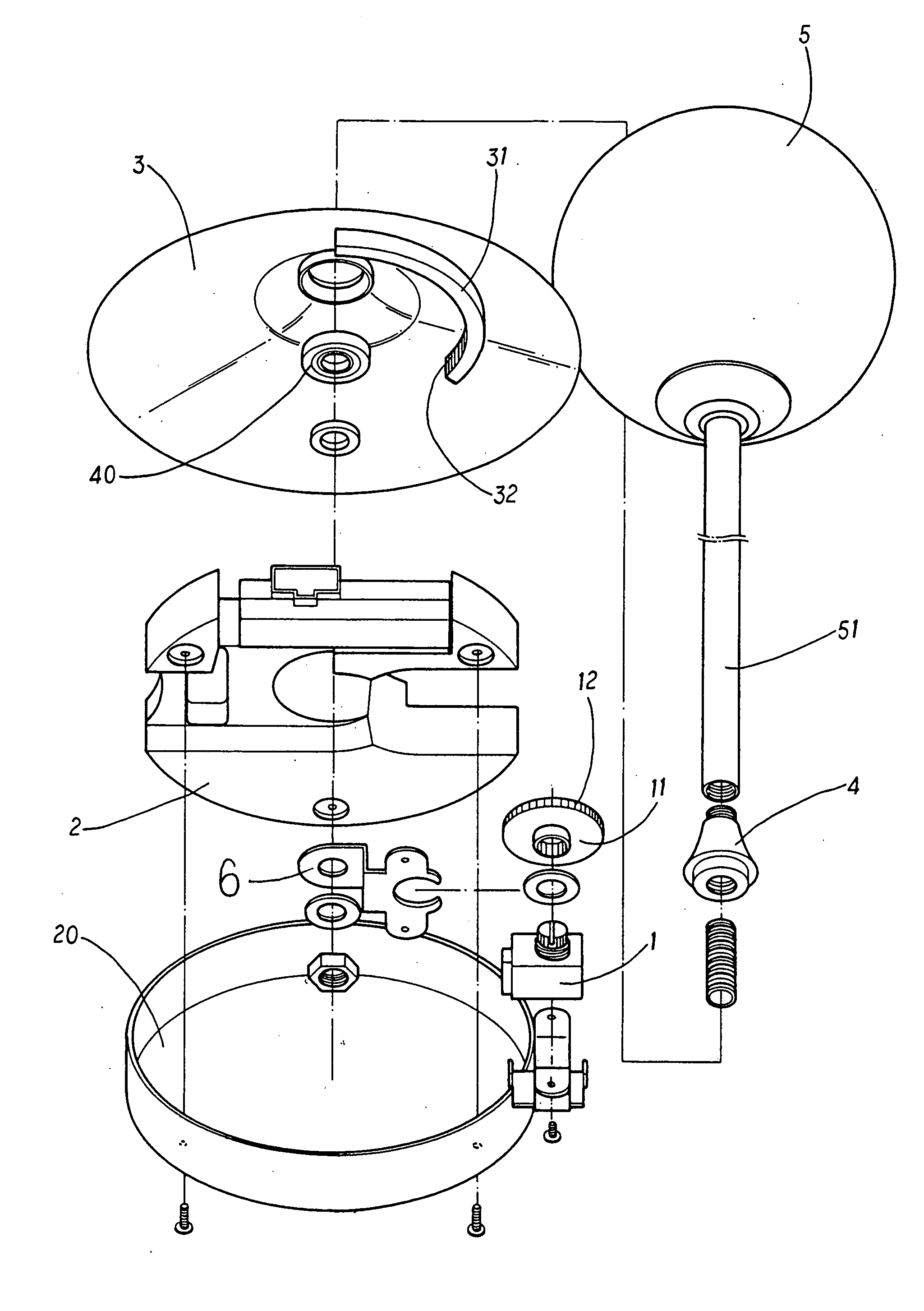
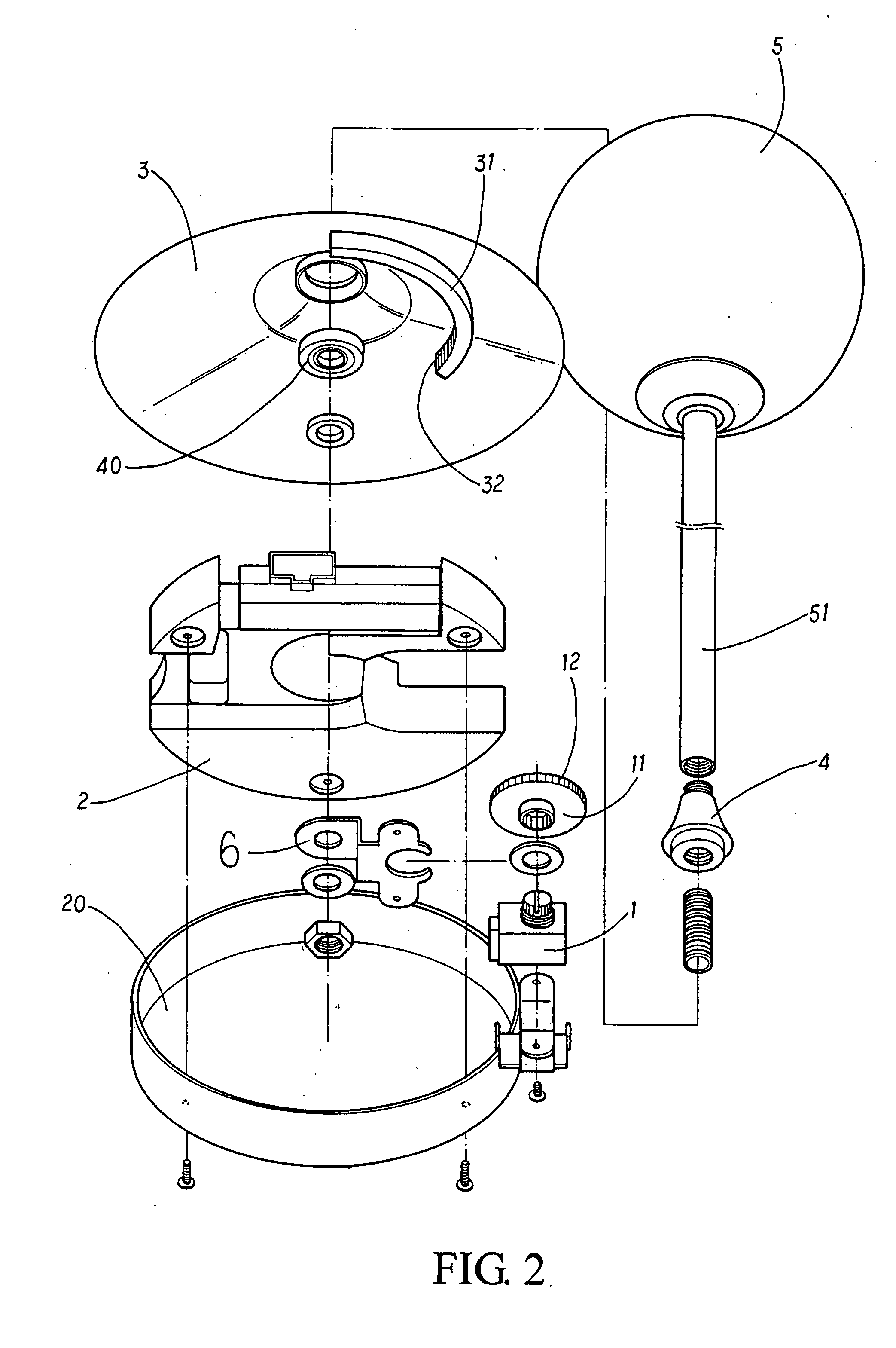
[0015] With reference to FIGS. 2 to 5, the present invention has the following elements.

[0016] A tube body 51 is engaged with a connector 40. A screw is screwed into a lower side of the connector 40. A lamp 5 is installed at a top of the tube body 51.

[0017] An upper cover 3 is located below the connector 4.

[0018] A bearing 40 is installed below the upper cover 3 and between the connector 4 and the upper cover 3. A cambered strip 31 is protruded from an inner surface of the upper cover 3. The cambered strip 31 has teeth 31.

[0019] A seat 2 is ...


PUM


Abstract

A rotation-controlled device for controlling actuation and de-actuation of the lamp comprises an upper cover; a cambered strip protruded from an inner surface of the upper cover; a seat installed below the upper cover by using a connector; a button installed to the seat and resisting against the cambered strip; the button being pushed to rotate by the cambered strip; and a light adjuster installed below the button and aside the locking piece; the actuation of the light adjuster being controllable by the button. A bearing is installed below the upper cover and between the connector and the upper cover. A bottom cover is installed below the seat. The cambered strip has teeth and the button has teeth. The one side of the cambered strip has a sticky surface and a periphery of the button has another sticky surface.

Description

FIELD OF THE INVENTION [0001] The present invention relates to lamp control device, and particular to a rotation-controlled lamp for controlling actuation and de-actuation of the lamp wherein a light adjuster is installed within the lamp seat and the actuation and de-actuation of the lamp can be achieved by rotating an upper cover. Thereby, the present invention can provide the lamp seat with a beautiful outlook. BACKGROUND OF THE INVENTION [0002] In the conventional lamp control, referring to FIG. 1, a light adjuster 61 is installed within a middle section of a lamp rod 62. The lamp rod has an upper section and a lower section. A round cylinder 63 is screwed to the lamp rod. A connection of the lamp rod 62 is installed with a long slot 64. The light adjuster 1 is installed within the long slot 64. Then the lamp rod 62 is locked to the round cylinder 63. Then the light adjuster 1 is positioned to the lamp rod 65. However, above mentioned structure has the following defects. Firstly,...

Claims


Application Information

Patent Timeline
Patent Type & Authority Applications(United States)
IPC IPC(8): F21V33/00F21V23/04F21S6/00F21V21/06
CPCF21S6/00F21V21/06F21V23/04
Inventor CHEN, MEIRIC
Owner CHEN MEIRIC
Why Eureka
Try Eureka