Multiple band antenna and antenna assembly

a multi-band antenna and antenna assembly technology, applied in the direction of collapsable antennas, resonant antennas, quick-releasable antenna elements, etc., can solve the problem of requiring valuable real esta

Inactive Publication Date: 2005-12-15
AMPHENOL T & M ANTENNAS
View PDF55 Cites 19 Cited by
  • Summary
  • Abstract
  • Description
  • Claims
  • Application Information

AI Technical Summary

Problems solved by technology

However, because antennas for such devices are tailored to particular bands, reception in more than one or two bands typically requires multiple mounted antennas.
This in turn requires valuable real estate on or in a portable device.

Method used


Image

  • Multiple band antenna and antenna assembly
  • Multiple band antenna and antenna assembly
  • Multiple band antenna and antenna assembly

Examples


Embodiment Construction

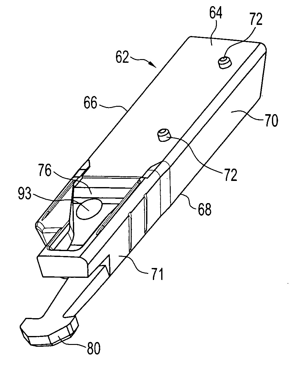
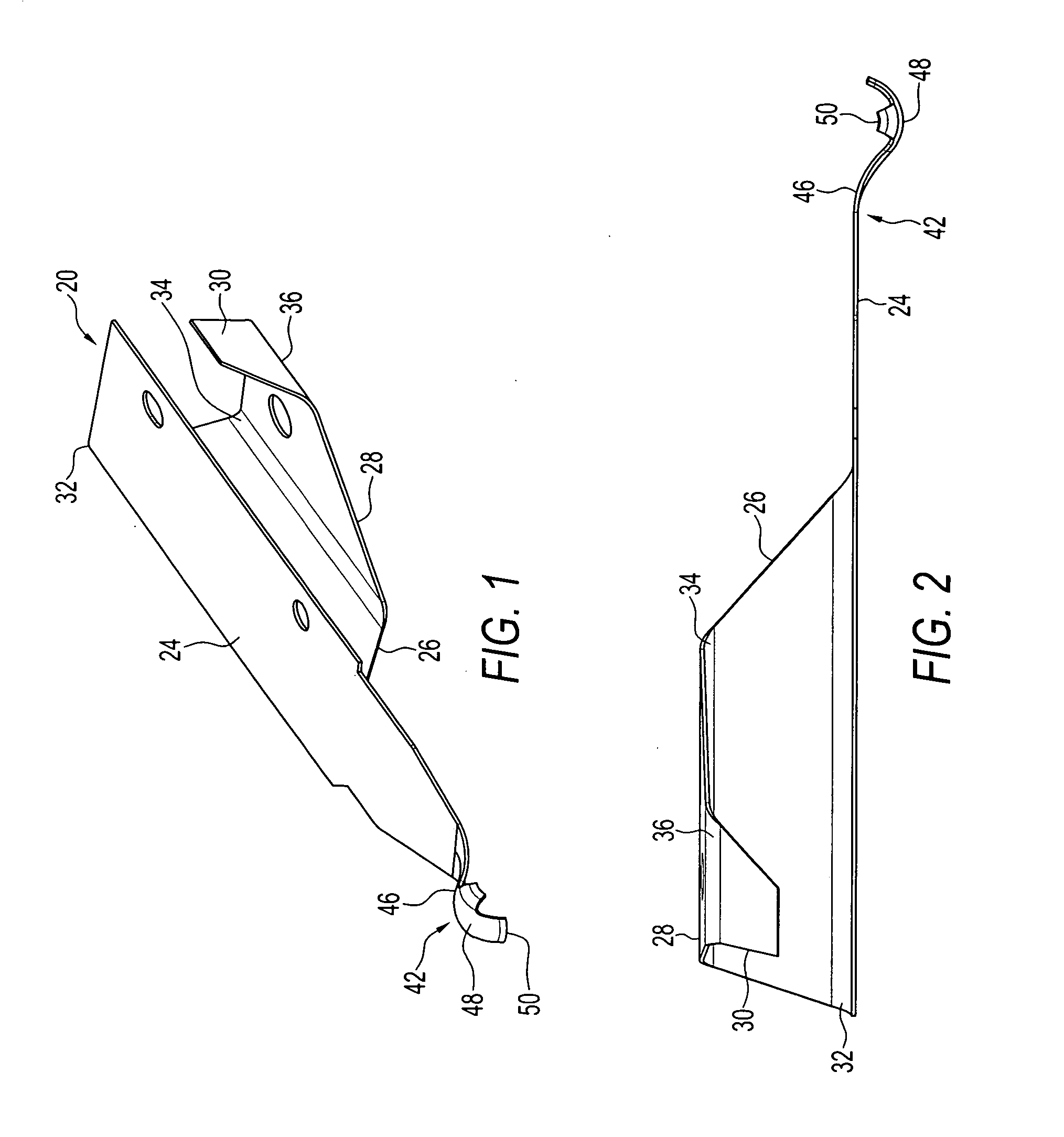
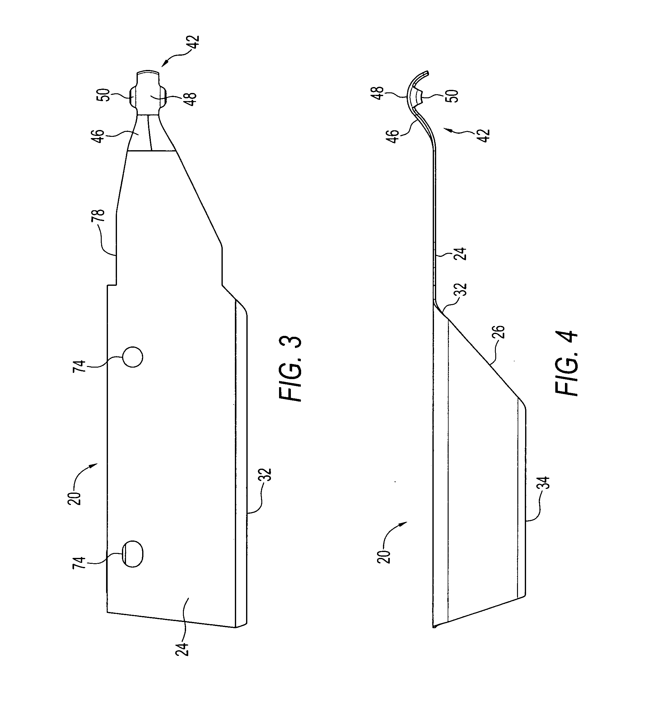
[0023] Preferred embodiments of the present invention include a multiple band antenna capable of reception across several, e.g., six or seven, bands. A preferred multiple band antenna adds a relatively small volume to a portable device. For example, a preferred multiple band antenna can be implemented as a short stubby antenna extending from a portable device.

[0024] Antenna reception in devices prior to the present invention typically has been based on a monopole principle, where an extended antenna provides a half-dipole and a ground plane such as a printed circuit board (PCB) of the mobile electronic device serves as the other half-dipole.

[0025] Preferred embodiments of the present invention include a multiple band antenna for a portable device. The antenna includes a piece of conductive metal including a half-bowtie portion shaped to define a monopole. A PCB provides the other half-dipole. Bowtie antennas have been used for television consoles and other typically stationary pro...


PUM


Abstract

Multiple band antenna for mounting to a portable device. The antenna comprises a piece of conductive metal including a half-bowtie portion shaped to define a monopole and folded to provide a plurality of planar surfaces together generally enclosing a volume. A flexible spring contact extends from the half-bowtie portion. The spring contact is configured for engaging a contact of the portable device.

Description

PRIORITY CLAIM [0001] The present application claims the benefit of U.S. Provisional Application Ser. No. 60 / 573,875, filed May 24, 2004, under 35 U.S.C. § 119.BACKGROUND OF THE INVENTION [0002] A field of the present invention is antennas for portable devices. [0003] Antennas currently being used for portable devices such as, but not limited to, portable communication devices, portable computing devices (including hand held computers and personal digital assistants), and portable computers, are optimized by design for reception of specific radio frequency bands. For example, particular portable devices may include GSM antennas (appr. range 824-960 MHz), GPS antennas (1575 MHz), DCS antennas (1710-1880 MHz), PCS antennas (1850-1990 MHz), 802.11b antennas (2.4-2.48 GHz), and / or 802.11a / g antennas (5.15-5.85 GHz). Still others may provide antennas in 3G range, for example, or in other frequency bands. [0004] However, because antennas for such devices are tailored to particular bands, ...

Claims


Application Information

Patent Timeline
Patent Type & Authority Applications(United States)
IPC IPC(8): H01Q1/24H01Q5/00H01Q9/40H01Q9/42
CPCH01Q1/088H01Q9/42H01Q9/40H01Q1/242H01Q1/24H01Q5/00
Inventor ZHANG, ZHIJUNLANGER, JEAN-CHRISTOPHESUTTER, ROBKFOURY, TONY
Owner AMPHENOL T & M ANTENNAS
Why Eureka
Try Eureka