Modulated current gas turbine engine starting system

Active Publication Date: 2005-12-22
PRATT & WHITNEY CANADA CORP
View PDF18 Cites 48 Cited by
  • Summary
  • Abstract
  • Description
  • Claims
  • Application Information

AI Technical Summary

Benefits of technology

[0011] The present invention advantageously provides a method and system to effectively start any type of engine under various

Problems solved by technology

The torque vs. speed characteristic of DC motors is fixed when the electric power supplied to the DC motors is predetermined and unchangeable, which is typically the case when batteries are used as the electric power source.
Thus, the starter is not always enabled to efficiently start the engine under all conditions.
This problem is more severe when an auxiliary power unit (APU) en

Method used


Image

  • Modulated current gas turbine engine starting system
  • Modulated current gas turbine engine starting system
  • Modulated current gas turbine engine starting system

Examples


Example

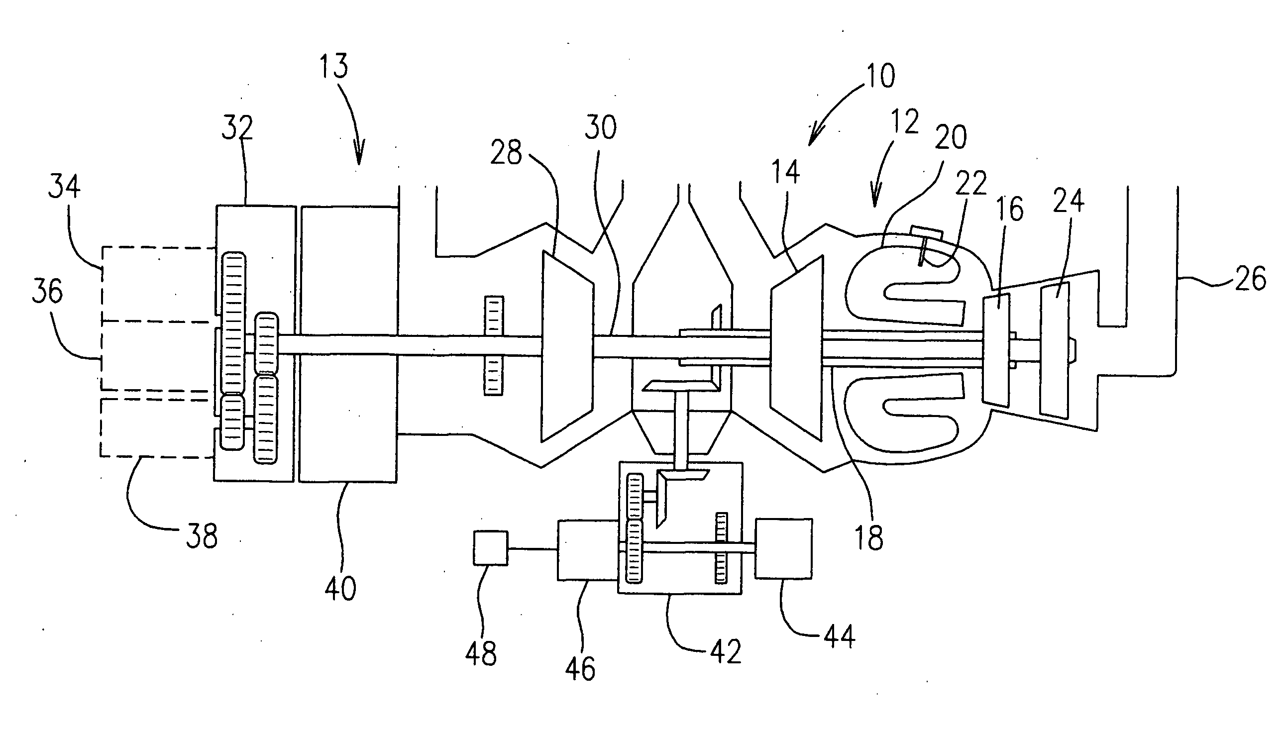
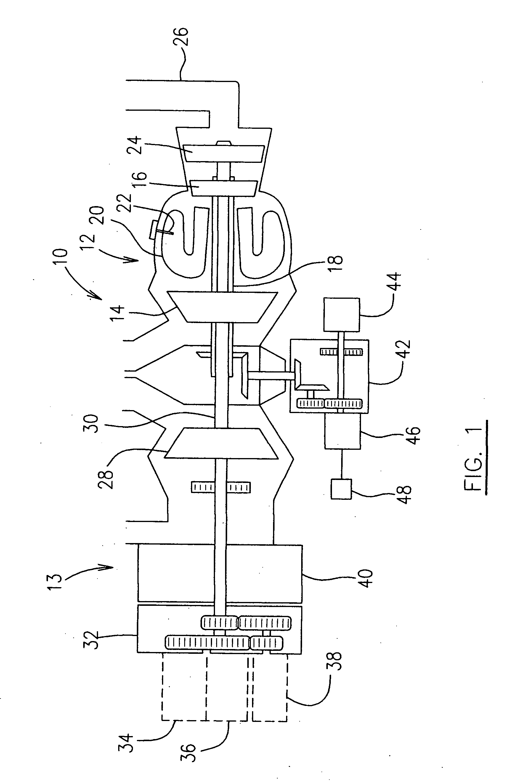
[0019] Referring to FIG. 1, a gas turbine engine 10, which is illustrated as a APU engine but can be any type of gas turbine engine, includes an embodiment of the present invention which will be further described with reference to other figures of the drawings. Engine 10 generally includes a core section 12 and a load section 13. In the core section 12 a high pressure compressor 14 is driven by a high pressure turbine 16 through a hollow shaft 18 in order to provide necessary air pressure and flow for combustion in an annular combustor 20. A plurality of fuel nozzles 22 (only one shown) are provided to inject fuel into the combustor 20 for combustion. The combustion gases discharged from the combustor 20 power the high pressure turbine 16 and also drive a power turbine 24, and are then discharged through an exhaust duct 26 (the engine outlet). The power turbine 24 rotates a load compressor 28 in the load section 13 through a shaft 30 in order to provide pneumatic power to the aircra...


PUM


Abstract

A method and an apparatus for starting a gas turbine engine under various conditions are used to distribute a varying total amount of electric power to at least one of a starter, a fuel heater and an oil heater while providing fuel.

Description

FIELD OF THE INVENTION [0001] The present invention relates to an aircraft gas turbine engine, and more particularly to a gas turbine engine starting system regulated with electric power supplied thereto. BACKGROUND OF THE INVENTION [0002] In an aircraft gas turbine engine, a starter motor applies torque to the engine's shaft in order to start the engine. As the shaft starts to rotate, air is inducted into the compressor, compressed and then discharged into the combustor. Concurrently, the engine's fuel control system feeds fuel into the combustor in accordance with a pre-programmed fuel schedule in order to precisely maintain the proper fuel / air ratio in the combustor, thereby achieving a light-off condition. After light-off, the starter motor torque is augmented by torque from the engine's turbine. Before reaching idling speed of the engine, the starter motor is shut off. This operation constitutes a starting cycle of a gas turbine engine. [0003] DC (Direct Current) motors are com...

Claims


Application Information

Patent Timeline
IPC IPC(8): F02C7/22F02C7/26F02C7/275F02C9/00F02M11/04
CPCF02C7/275
Inventor O'CONNOR, RICHARD JOHN
Owner PRATT & WHITNEY CANADA CORP
Why Eureka
Try Eureka