Work machine joystick control system

a control system and work machine technology, applied in the direction of mechanical control devices, manual control with single controlling member, instruments, etc., can solve the problems of poor quality and/or low production, fatigue of operators, and relatively complicated operation of work machines and work implements

Active Publication Date: 2005-12-22
CATERPILLAR INC
View PDF45 Cites 48 Cited by
  • Summary
  • Abstract
  • Description
  • Claims
  • Application Information

AI Technical Summary

Benefits of technology

The patent describes a control system for a work machine with an articulated joint and a work implement. The system includes two levers, one of which controls the speed of articulation and the other the speed of rotation of the work implement. The levers have operator control devices. The technical effect of this system is to provide a more intuitive and efficient way of controlling the work machine, allowing for faster and more precise operation.

Problems solved by technology

The technical problem addressed by this patent is reducing operator fatigue and improving the quality and efficiency of work machines and their attachments by designing a better operator interface that reduces the number of controls needed to achieve all necessary functions while maintaining optimal performance.

Method used


Image

  • Work machine joystick control system
  • Work machine joystick control system
  • Work machine joystick control system

Examples


Embodiment Construction

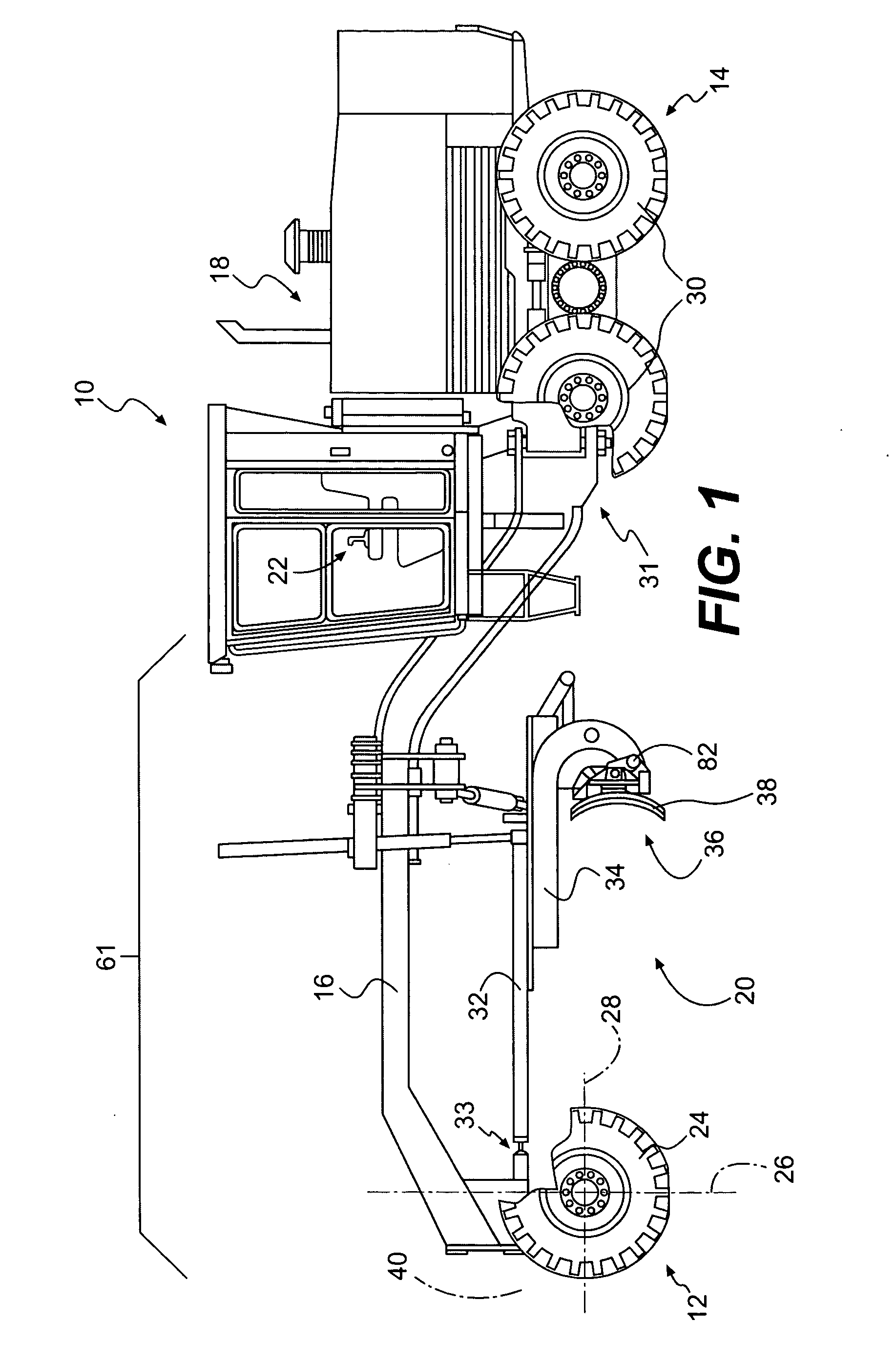
[0016] An exemplary embodiment of a work machine 10 is illustrated in FIG. 1. Work machine 10 may be a motor grader, a backhoe loader, an agricultural tractor, a wheel loader, a skid-steer loader, or any other type of work machine known in the art. Work machine 10 may include a steerable traction device 12, a driven traction device 14, a frame 16 connecting steerable traction device 12 to driven traction device 14, a power source 18 supported by driven traction device 14, and a transmission (not shown) configured to transmit power from power source 18 to driven traction device 14. Work machine 10 may also include a work implement such as, for example, a drawbar-circle-moldboard assembly (DCM) 20, and a control system 22.

[0017] Steerable traction device 12 may include one or more wheels 24 located on each side of work machine 10 (only one side shown). Alternately, steerable traction device 12 may include tracks, belts, or other traction devices. Wheels 24 may be rotatable about a ve...


PUM


Abstract

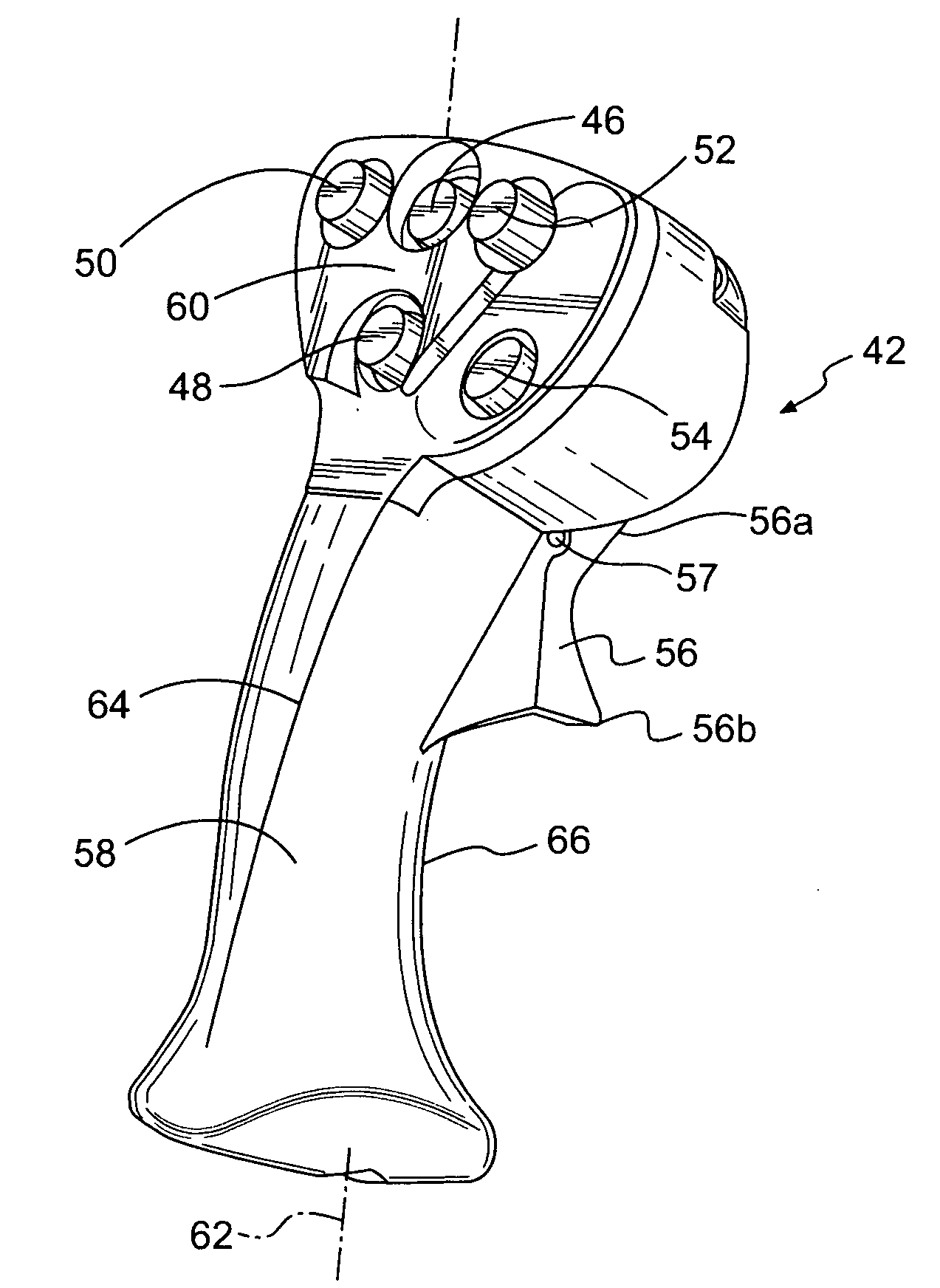
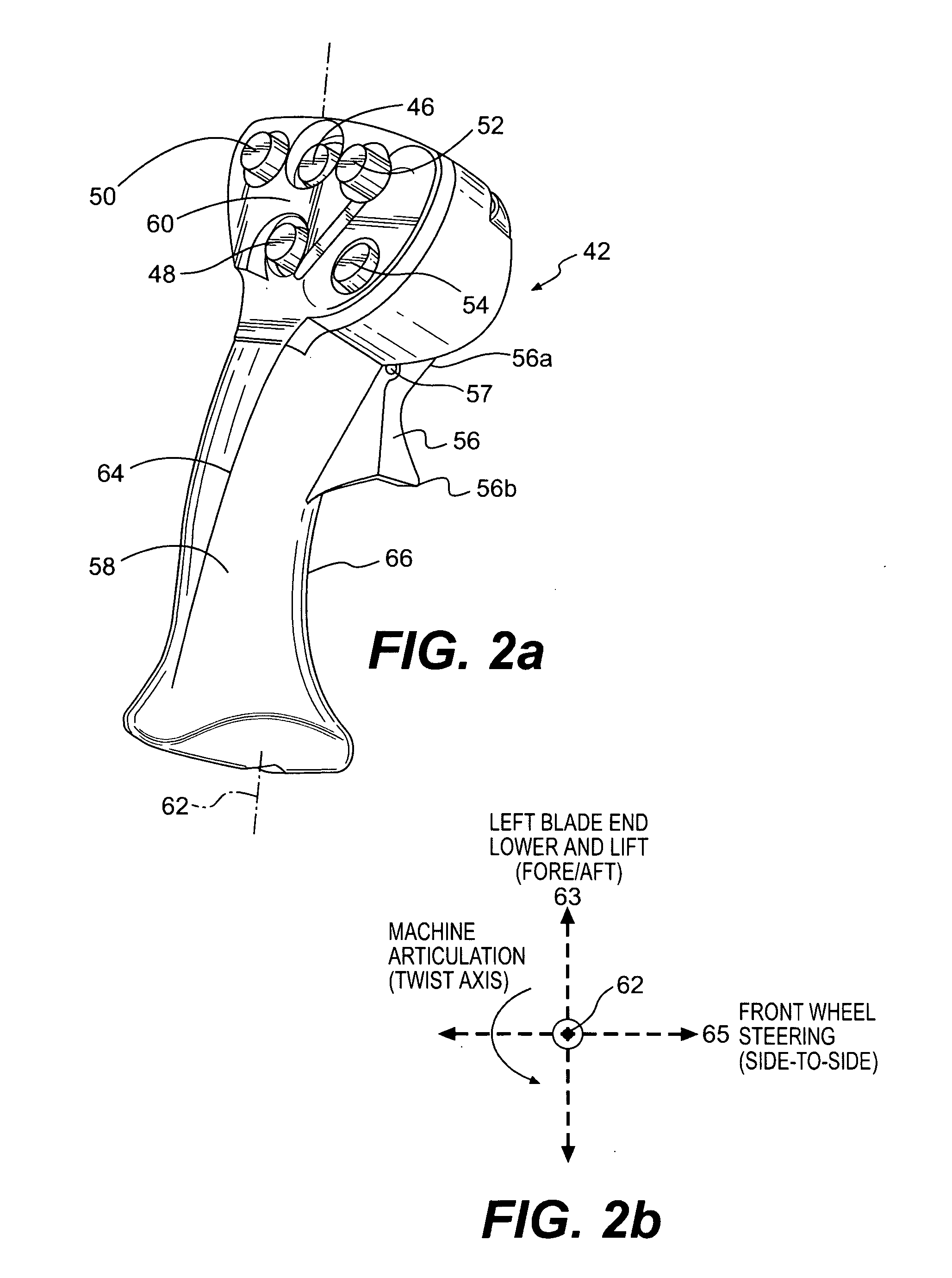
A control system for a work machine, having an articulated joint and a work implement with at least one axis of rotation, has a first lever with a first longitudinal axis. A twist angle of the first lever about the first longitudinal axis is related to an articulation speed of the work machine. The control system also has a second lever having a second longitudinal axis. A twist angle of the second lever about the second longitudinal axis is related to a rotation speed of the work implement about the at least one axis of rotation. A plurality of operator control devices are disposed on the first and second levers.

Description


Claims


Application Information

Patent Timeline
Owner CATERPILLAR INC
Why Eureka
Try Eureka