
Side view mirror with light emitting trim ring

a technology of light-emitting trim rings and mirrors, which is applied in the direction of fixed installations, lighting and heating devices, lighting support devices, etc., can solve the problems of limited success of prior art attempts

Inactive Publication Date: 2005-12-22
UNITED GLOBAL SOURCING
View PDF14 Cites 60 Cited by
  • Summary
  • Abstract
  • Description
  • Claims
  • Application Information

AI Technical Summary

Problems solved by technology

These prior art attempts have met with limited success owing to the increased complexity associated with modifying mirror surfaces to accommodate LEDs or the alignment of components.

Method used


Image

  • Side view mirror with light emitting trim ring
  • Side view mirror with light emitting trim ring
  • Side view mirror with light emitting trim ring

Examples


Embodiment Construction

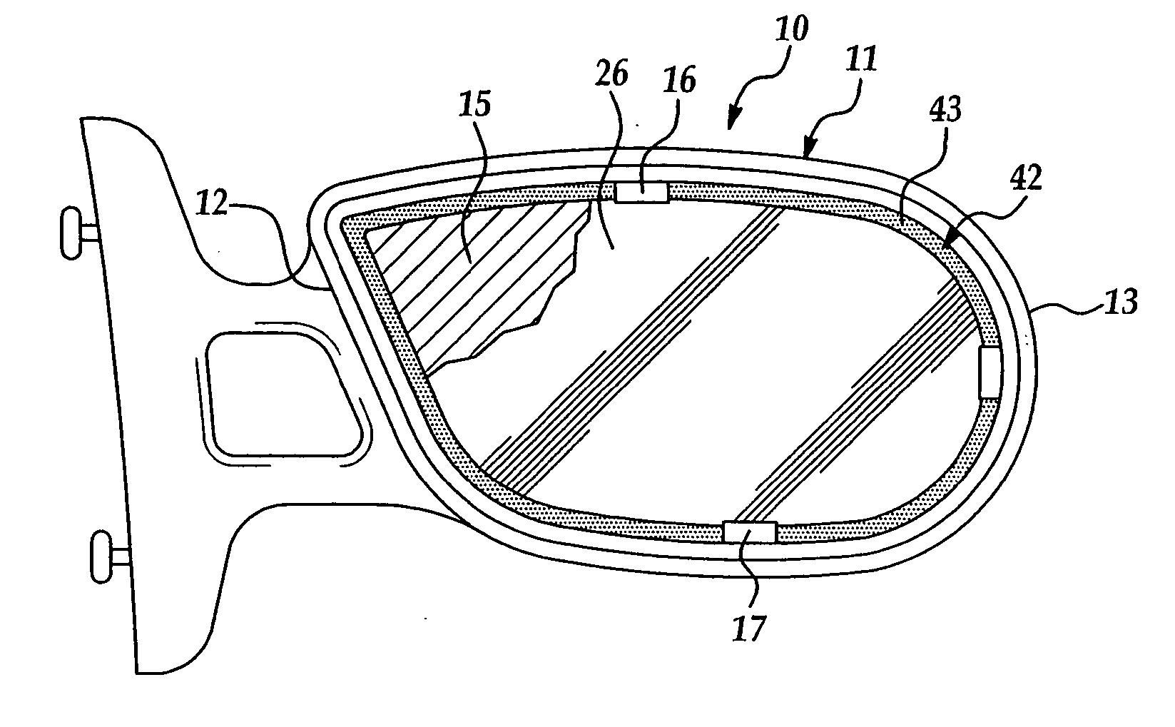
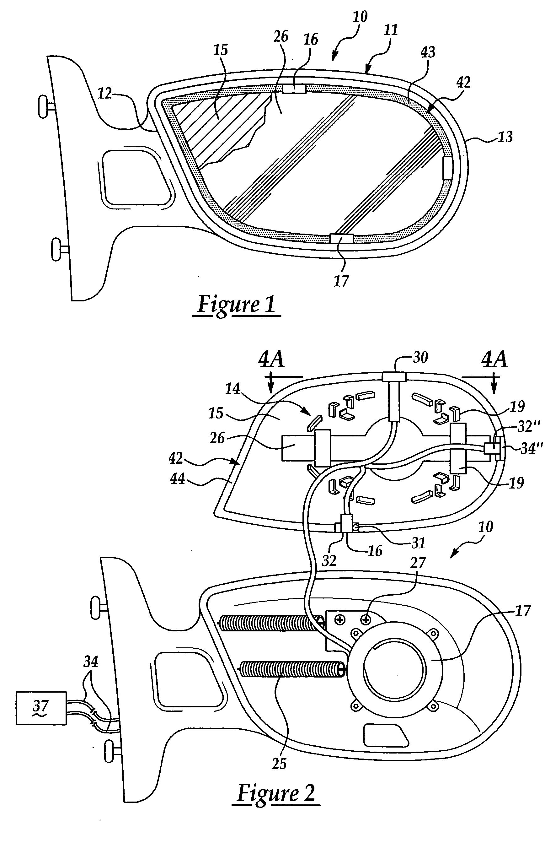
[0011] A light emitting mirror assembly for a vehicle includes a housing and a support element for supporting a mirror disposed within the housing. The housing has a proximal side which is proximal to an exterior side portion of a vehicle, and a distal side which is distal to the exterior side portion of the vehicle. The mirror has a front reflective surface, a rear surface, and edges, the combined lengths of the edges defining the perimeter of the mirror. The proximal side edge is proximal to an exterior side portion of a vehicle, and the distal side edge is distal to the exterior side portion of the vehicle.

[0012] The support element includes a backing portion and a trim portion. The backing portion is in connection with the rear surface of the mirror. Typically, the backing portion is adhered to the rear surface of the mirror by an adhesive such as glue, double-sided adhesive tape, and the like. The trim portion is connected to and extends along at least a portion of the perimet...


PUM


Abstract

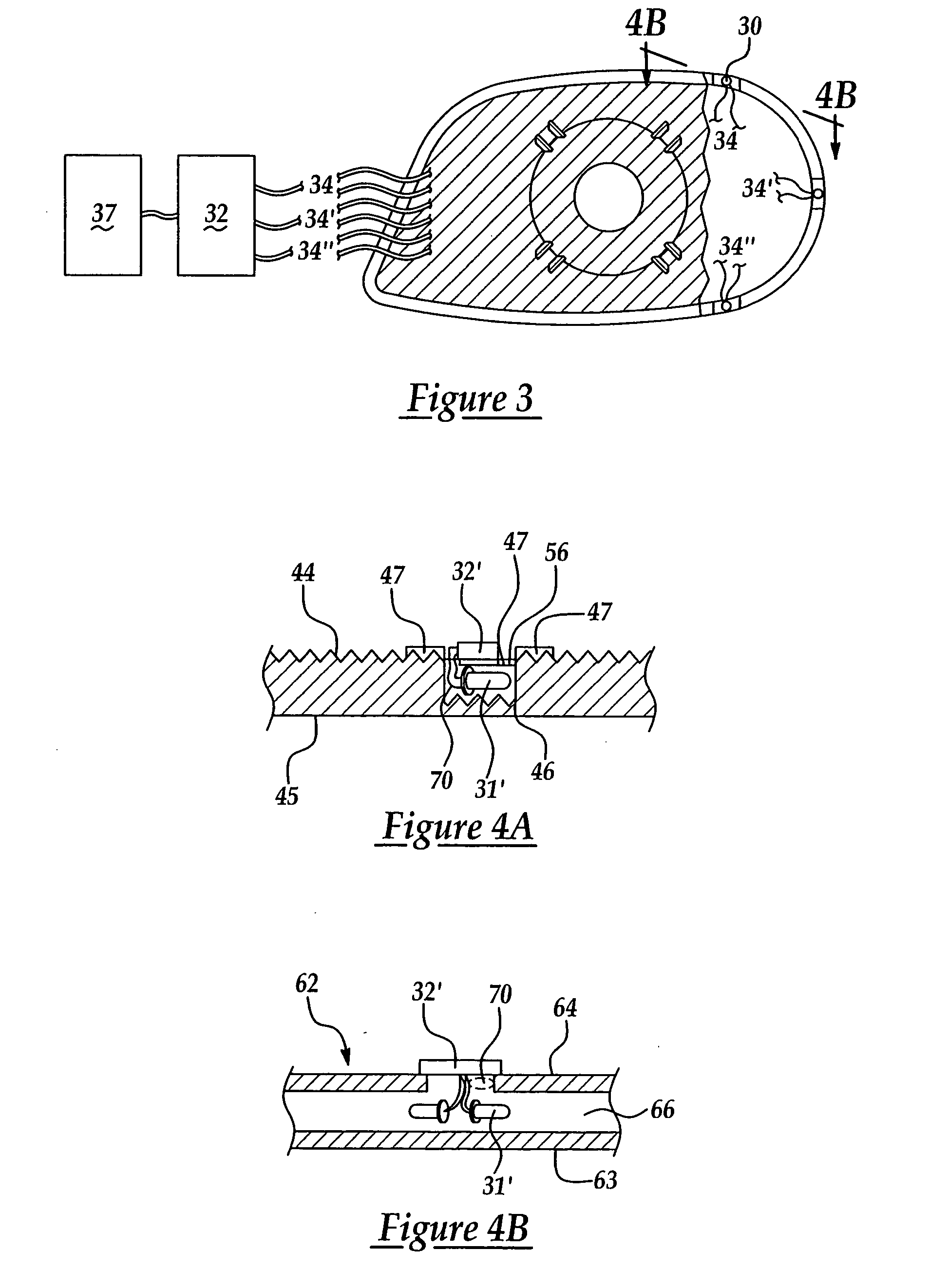
A light emitting mirror assembly for a vehicle is intended to side mount to the vehicle and includes a support element that provides a backing for the mirror and a trim portion that encompasses at least in part the perimeter of a mirror. The trim portion has a transparent or translucent light source housing cavity. A light source is disposed in the light source housing cavity and electrically connected to the vehicle such that light is emitted from the light source in response to an activation signal. A trim portion can include multiple light source housing cavities each of which can contain one or more light sources. The illuminated trim ring offers a mirror mounted turn signal indicator, puddle light, brake light, or decorative displays without resort to modifying the mirror face or reflections from the mirror face.

Description

RELATED APPLICATION [0001] This application claims priority of U.S. Provisional Patent Application Ser. No. 60 / 515,633 filed Oct. 30, 2003, which is incorporated herein by reference.FIELD OF THE INVENTION [0002] The present invention generally relates to a side view vehicle mirror that incorporates a turn indicator signal, and in particular to a side view vehicle mirror that incorporates a turn indicator signal in a trim ring about the mirror. BACKGROUND OF THE INVENTION [0003] While turn indicators have traditionally been located at the corners of a vehicle to signal lane change or vehicle turning, there is now an appreciation that additional turn indicators are needed on side view mirrors. A side view mirror mounted turn indicator affords added visibility to a following vehicle, especially in situations where the following vehicle is close or when the equipped vehicle is pulling a trailer. [0004] There have been numerous devices developed that incorporate light emitting diode (LED...

Claims


Application Information

Patent Timeline
Patent Type & Authority Applications(United States)
IPC IPC(8): B60Q1/26B60R1/12
CPCB60R1/1207B60Q1/2665
Inventor EISENBRAUN, KENNETH D.
Owner UNITED GLOBAL SOURCING
Learn More