Tool handle having tool receiving structure

a tool and handle technology, applied in the field of tool handles, can solve the problems of not being easily operated by users, all the tool members may have a good chance of being disengaged from the handle inadvertently, and the device may not be easily fetched or grasped by users

Inactive Publication Date: 2005-12-29
LIAO YOUN CHYUAN
View PDF4 Cites 39 Cited by
  • Summary
  • Abstract
  • Description
  • Claims
  • Application Information

AI Technical Summary

Benefits of technology

[0011] The primary objective of the present invention is to provide a tool handle including a tool receiving structure fo

Problems solved by technology

However, when the cover is opened or disengaged from the handle, not only the tool members required to be fetched but also the other tool members may all be exposed, such that all of the tool members may have a good chance to be disengaged from the handle inadvertently.
In addition, the cover should be disengaged and separated from the handle, and may thus have a goo

Method used


Image

  • Tool handle having tool receiving structure
  • Tool handle having tool receiving structure
  • Tool handle having tool receiving structure

Examples


Embodiment Construction

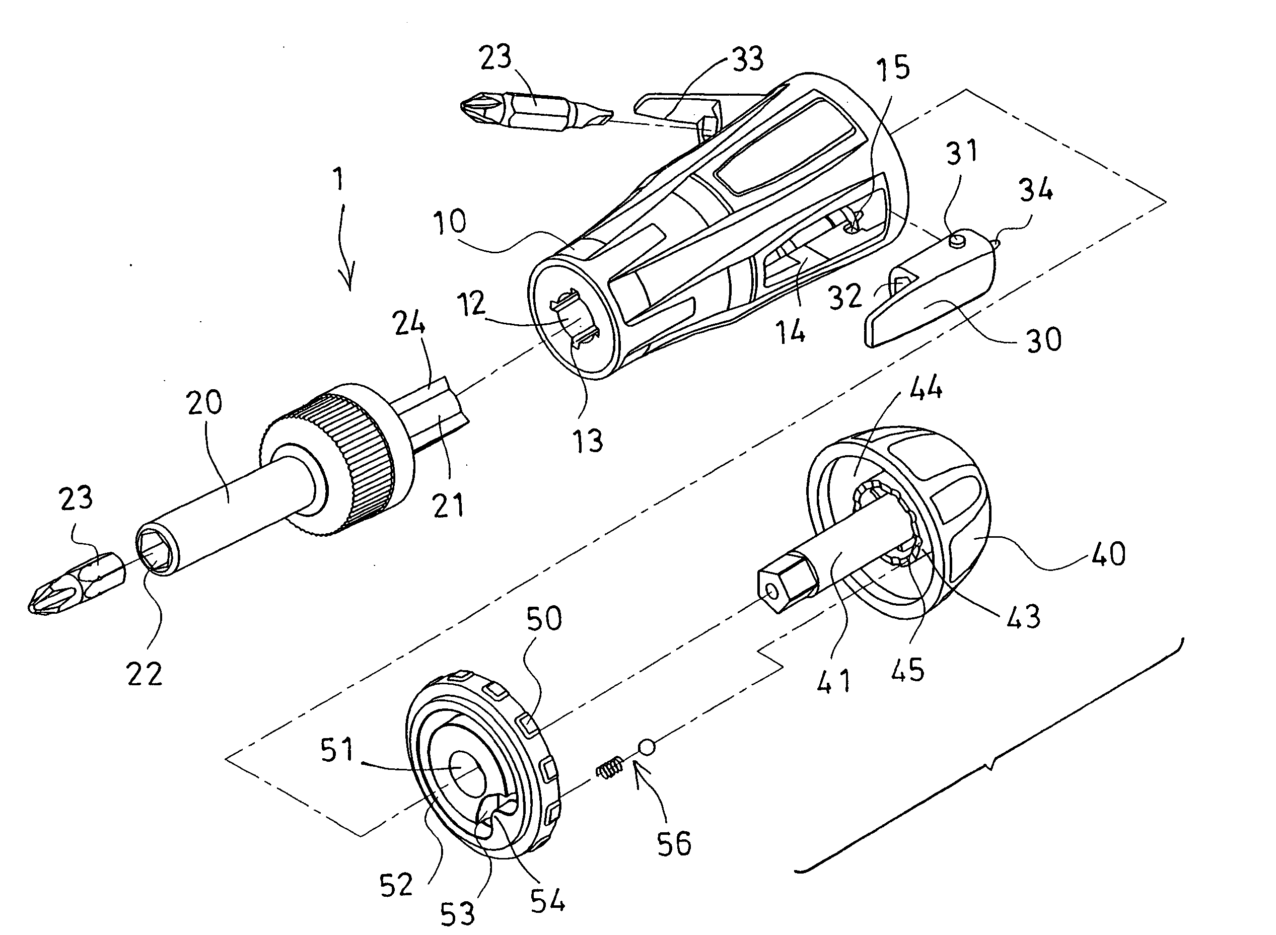
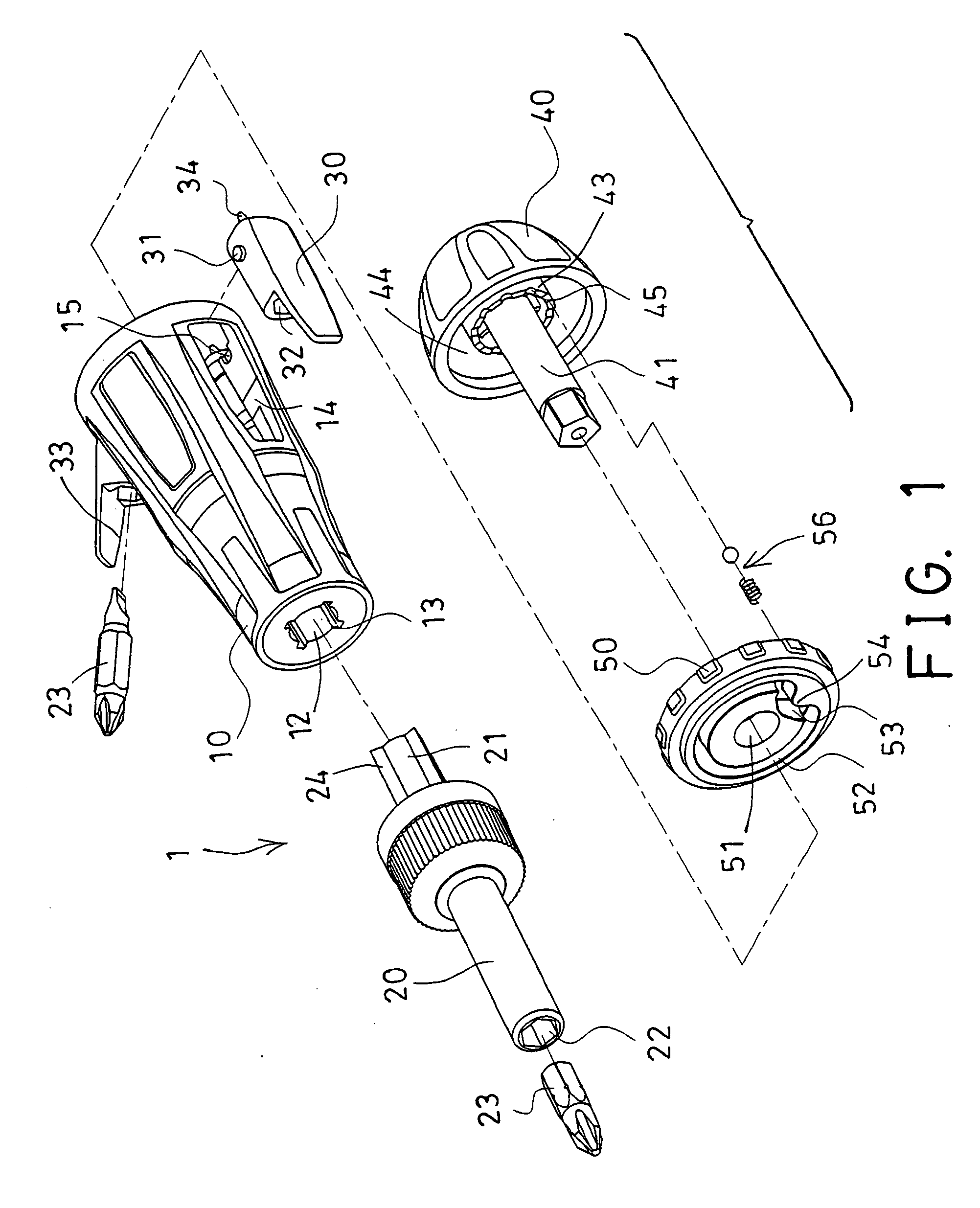
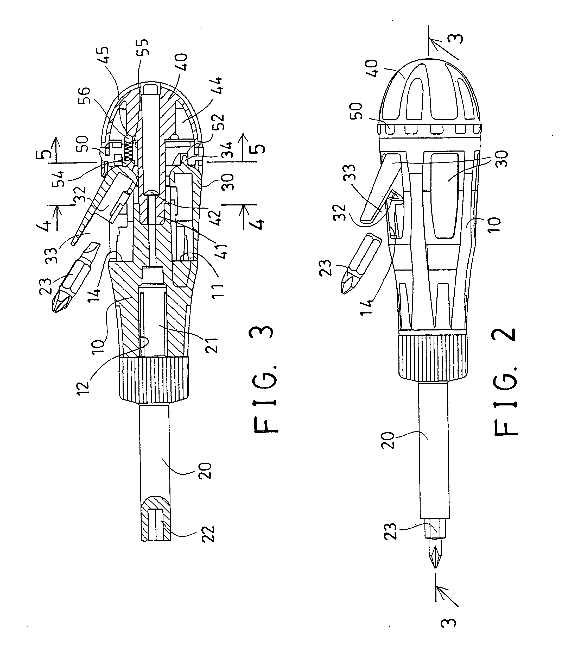
[0031] Referring to the drawings, and initially to FIGS. 1-5, a tool handle 1 in accordance with the present invention comprises a handle body or handle member 10 including a chamber 11 formed therein (FIGS. 3, 5), and including a bore 12 formed in one end, such as formed in the front end thereof (FIGS. 1, 3), for receiving and anchoring or securing one end or rear end 21 of a driving stem 20 which includes an engaging hole 22 formed in the other end thereof for receiving tool members 23 therein.

[0032] The rear end 21 of the driving stem 20 may be detachably attached or anchored or secured to the handle body or handle member 10 with such as latches (not shown), ribs or nibs 24, or the like, which may be engaged into the corresponding slots or grooves 13 of the handle member 10, to solidly secure. or anchor the driving stem 20 to the handle member 10, and to prevent the driving stem 20 from being rotated relative to the handle member 10. The attachment or the engagement of the drivi...


PUM


Abstract

A tool handle includes a handle member having a number of compartments formed in an outer peripheral portion, a number of holders rotatably received in the compartments of the handle member and each having an engaging hole for receiving a tool member, and a rotary member rotatably attached to the handle member. The holders each includes an extension. The rotary member includes an actuator or a peripheral groove for selectively engaging with the extensions of the holders, and for selectively rotating the holders relative to the handle member to an outwardly opening and working position, by rotating the rotary member relative to the handle member.

Description

BACKGROUND OF THE INVENTION [0001] 1. Field of the Invention [0002] The present invention relates to a tool handle, and more particularly to a tool handle having a tool receiving structure for suitably receiving tool members therein, and for allowing the tool members to be easily fetched or grasped by the users. [0003] 2. Description of the Prior Art [0004] Typical tool devices comprise a handle including a driving shank extended therefrom, for rotating and for operating the driving shank to rotate or to drive fasteners, or other tool members. The handles of some of the tool devices may comprise one or more compartments formed therein for receiving or storing various tool members therein. [0005] Normally, the typical tool devices may comprise a cover detachably or openably attached thereto, to selectively enclose the compartments thereof, and to selectively enclosing and shielding the tool members within the compartments of the handles of the tool devices. The tool members may be fe...

Claims


Application Information

Patent Timeline
IPC IPC(8): B25B23/16B25G1/06B25G1/08
CPCB25G1/085B25G1/066
Inventor LIAO, YOUN CHYUAN
Owner LIAO YOUN CHYUAN
Why Eureka
Try Eureka