Tool box

a tool box and tool technology, applied in the field of tool boxes, can solve the problems of not tool members may not be easily gripped or fetched by users, tool members may not be etc., and achieve the effect of being easily gripped or fetched by users

Inactive Publication Date: 2008-05-20
JEOUTAY LIU INDAL
View PDF6 Cites 23 Cited by
  • Summary
  • Abstract
  • Description
  • Claims
  • Application Information

AI Technical Summary

Benefits of technology

[0011]The primary objective of the present invention is to provide a tool box including a movable or slidable or spring-biased holder for movably supporting one or more tool bits, sockets or other tool members therein, and for selectively moving the tool members out of the tool box and for allowing the tool members to be easily gripped or fetched by the users.

Problems solved by technology

However, normally, the tool members may include only a short or tiny end portion extended out of the cavities or the socket openings of the receptacle, such that the tool members may not be easily gripped or fetched by the users.
However, when the aperture of the cover has been rotated and aligned with one of the tool members, the selected tool member also may not be moved out of the cavities or the socket openings of the receptacle, such that the tool members also may not be easily gripped or fetched by the users.
However, similarly, when the gate aperture of the bit gate of the bit cap has been rotated and aligned with one of the tool members, the selected tool member also may not be moved out of the cavities or the socket openings of the driver handle, such that the tool members also may not be easily gripped or fetched by the users.

Method used


Image

  • Tool box
  • Tool box
  • Tool box

Examples


Embodiment Construction

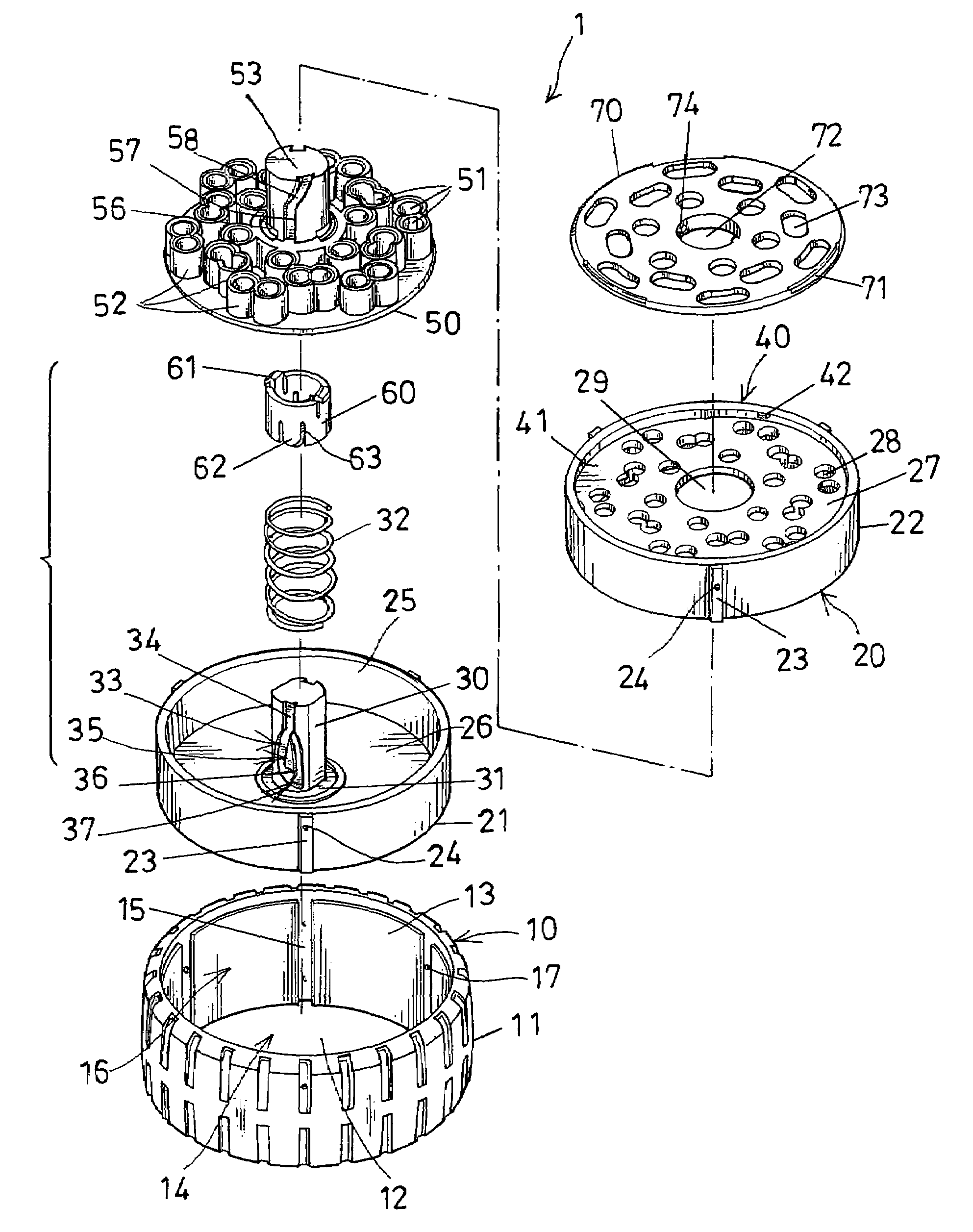
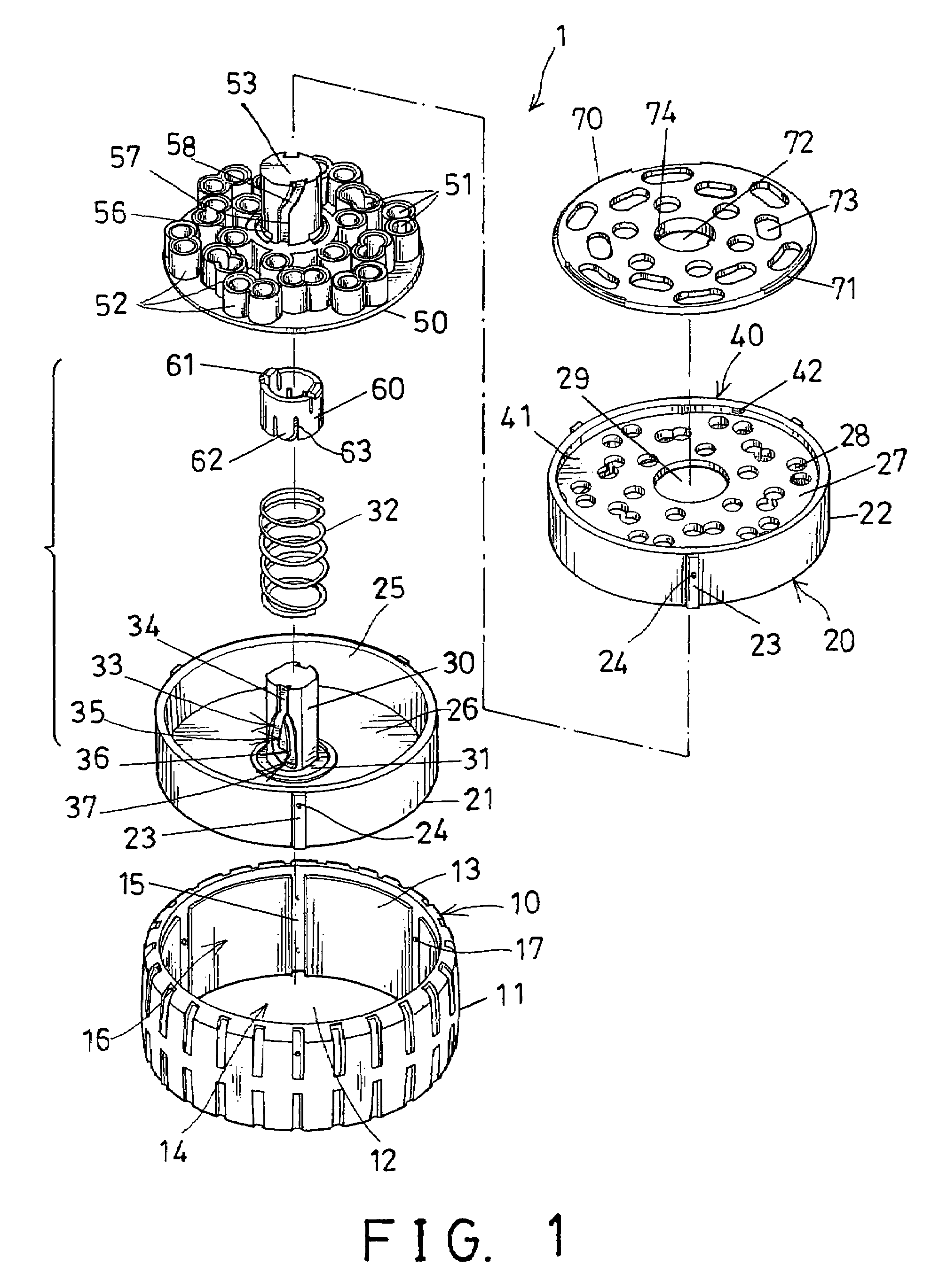
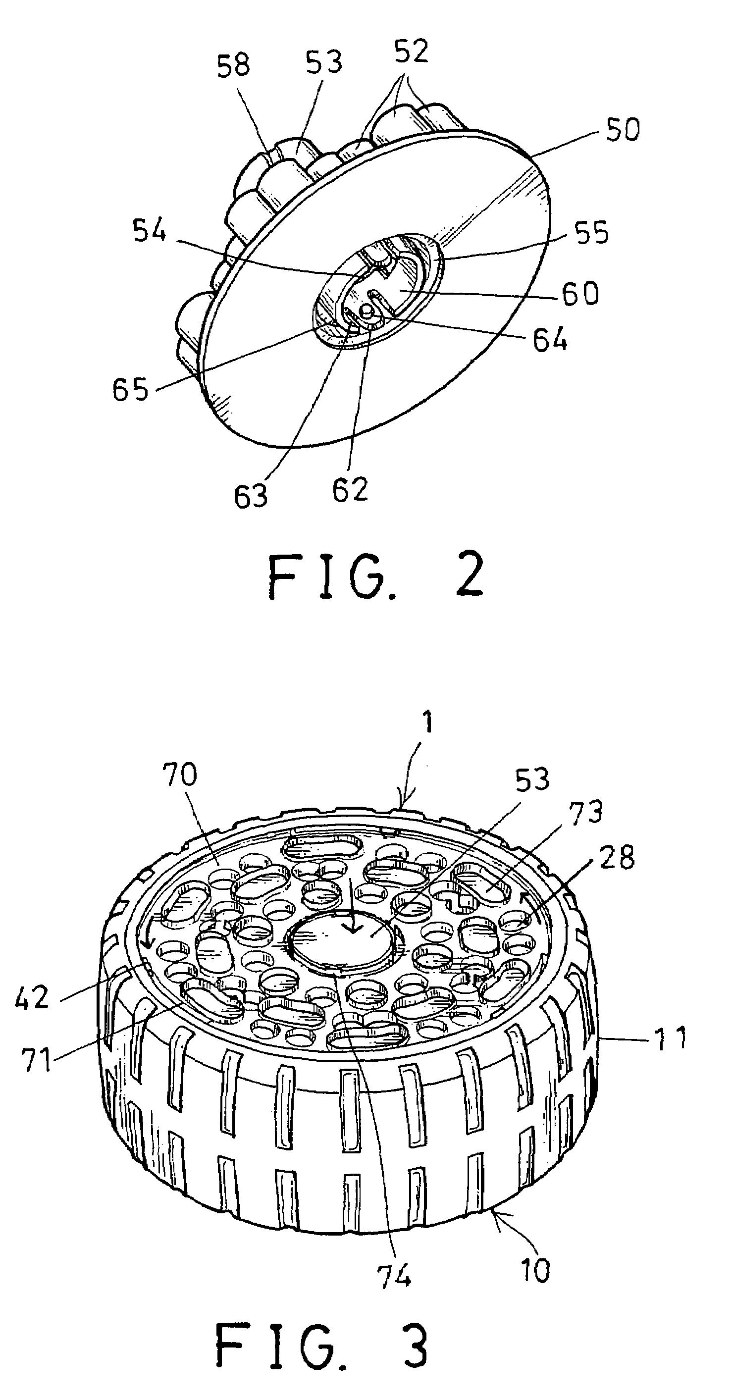
[0029]Referring to the drawings, and initially to FIGS. 1-3, a tool box 1 in accordance with the present invention comprises a receptacle 10 including an outer container 11 having a hollow chamber 12 formed therein and preferably having an open top 13 and / or an open bottom 14 formed therein, best shown in FIG. 1. The outer container 11 includes one or more vertical or longitudinal channels 15 formed in an inner peripheral surface 16 thereof, and one or more catches or cavities 17 extended therefrom or formed therein.

[0030]The receptacle 10 further includes a housing 20 having such as a lower casing 21 and an upper casing 22, received or engaged into the hollow chamber 12 of the outer container 11, and secured to the outer container 11 with such as force-fitted engagements. It is preferable that the lower and the upper casings 21, 22 each includes one or more vertical or longitudinal ribs 23 extended outwardly therefrom, for force-fitting into the corresponding channels 15 of the out...


PUM


Abstract

A tool box includes a housing having a number of orifices formed in an upper wall, and a carrier slidably received in the housing and having a number of socket openings for receiving tool members. The carrier is slidable relative to the housing for selectively moving the tool members in and out of the housing. A spring member may be engaged between the housing and the carrier, for biasing the carrier to move the tool members out of the housing. The carrier includes a bore for slidably receiving a guide post of the housing, and for guiding the carrier to move up and down relative to the housing. An anchoring device may anchor the carrier to the housing at the inwardly storing position.

Description

BACKGROUND OF THE INVENTION[0001]1. Field of the Invention[0002]The present invention relates to a tool box, and more particularly to a tool box having a movable or spring-biased holder for movably supporting tool bits, sockets or other tool members therein.[0003]2. Description of the Prior Art[0004]Typical tool boxes comprise a receptacle including a number of cavities or socket openings formed therein for receiving tool bits, sockets or other tool members therein. Normally, the tool bits or the sockets or the other tool members may include an end portion extended out of the cavities or the socket openings of the receptacle, for allowing the tool members to be gripped or fetched by the users and to be removed from the cavities or the socket openings of the receptacle.[0005]However, normally, the tool members may include only a short or tiny end portion extended out of the cavities or the socket openings of the receptacle, such that the tool members may not be easily gripped or fetc...

Claims


Application Information

Patent Timeline
Patent Type & Authority Patents(United States)
IPC IPC(8): B65D85/28
CPCB25H3/003
Inventor LIU, KUO CHEN
Owner JEOUTAY LIU INDAL
Why Eureka
Try Eureka