
Layer-a to MPLS service mediation architecture

Inactive Publication Date: 2005-12-29
RPX CLEARINGHOUSE
View PDF12 Cites 32 Cited by
  • Summary
  • Abstract
  • Description
  • Claims
  • Application Information

AI Technical Summary

Benefits of technology

[0016] One advantage of the mapped mode is the flexibility it provides in identifying the Forwarder on the MPLS network. The Forwarder identifiers on the MPE can encode a Layer-2 address that is routable within the Layer-2 network. With respect to the MPLS network, the Layer-2 address is treated as a bit string. In particular, the MPLS network need not have any knowledge that the bit string contains a Layer-2 address, nor that the MPLS network is required to know what type of address is being used. Further, no modifications are required to existing pseudowire / L2VPN signaling mechanisms.
[0017] Another advantage of the mapped mode is that it does not require the L2PE and the native Layer-2 address to encode and to know a priori the IP address of the MPE. Thus, this mode can support addressing plans other than ATM NSAP and provides address mobility on the MPE side. It also follows that the mapped mode can take advantage of an auto-discovery mechanism where IP addresses of MPEs are discovered by MMEs along with their associated set of attachment identifiers. Another advantage of this model is that it offers benefits of using Generalized ID FEC as described in [L2VPN-SIG], including service mobility, service resiliency with different AII, and offloads the operator from managing, on the MPLS network, Forwarder identifiers that are relevant only to the Layer-2 network.
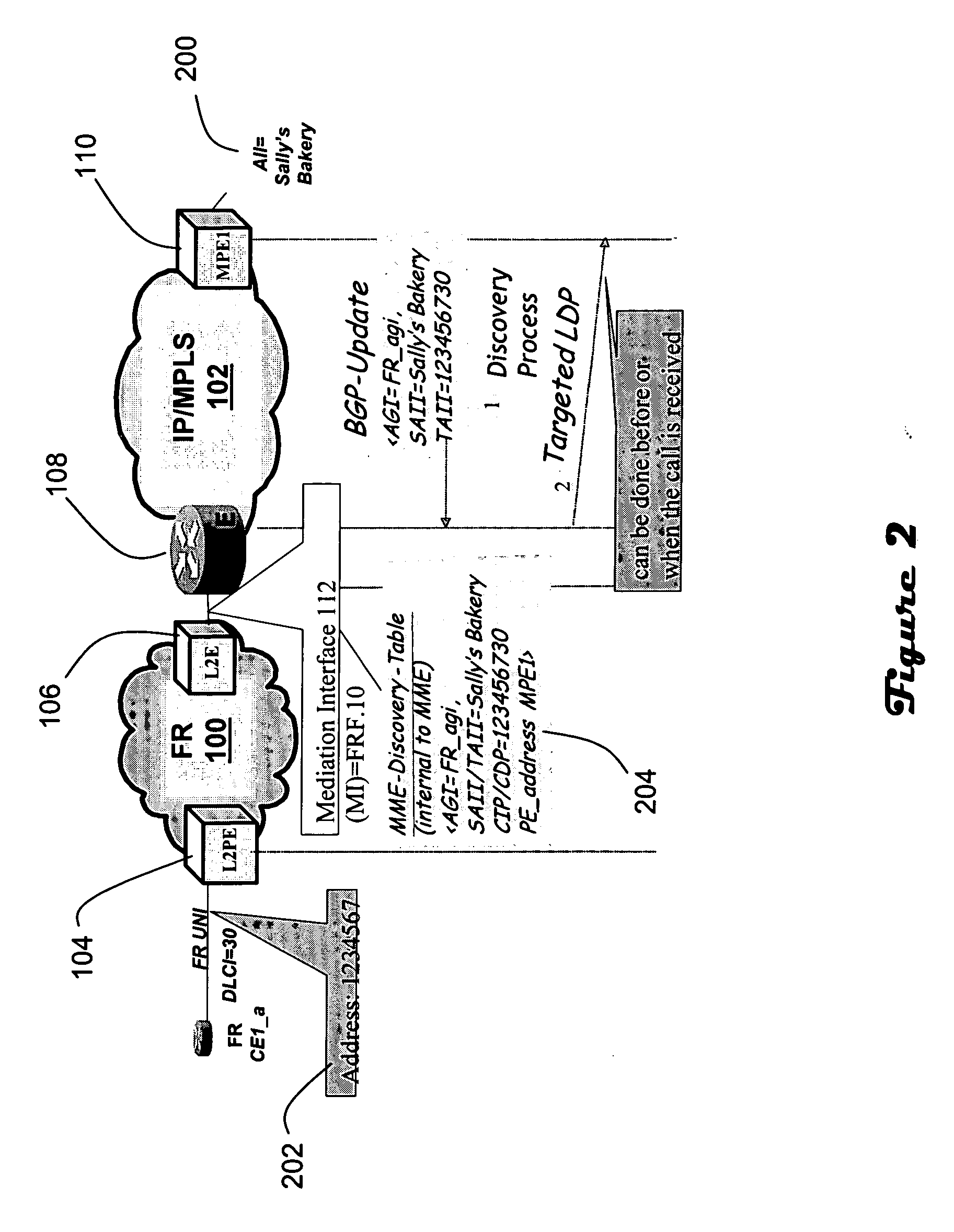
[0018] In an alternative embodiment an auto-discovery mechanism is employed to facilitate the mapped mode. Auto-discovery enables the Provider to support service endpoint mobility of the Layer-2 endpoints residing on the MPLS core network. Further, auto-discovery enables the MME to dynamically learn the set of remote endpoints with their MPE IP addresses. Auto-discovery also enables the L2PE to use any native layer 2 addressing plan without requiring synchronization between the MPLS core network management and Layer-2 network operations in terms of address management of the MPE devices (i.e., any change to MPE addressing, etc does not require configuration changes to the layer 2 network connections). Further, for calls originating from the MPEs and destined to the Layer-2 networks, the use of an auto-discovery mechanism allows the MPEs to discover the set of MME addresses and the set of AGIs supported within these MMEs.

Problems solved by technology

Since it would be quite costly to deploy parallel networks, service providers often deploy IP and MPLS based equipment in the same network with legacy equipment based on Layer-2 protocols.
However, the unmapped mode has some disadvantages.
The unmapped mode disadvantageously restricts the set of Forwarders on the MPE devices to only those that are relevant to the Layer-2 network.
Indeed, it is not possible for the MPLS operator to configure two separate Forwarders for the same mediated service on two different MPEs with the same or different VPI.VCI / DLCI values or port numbers.
Finally, the unmapped mode does not offer the ability to perform address mobility within the MPLS network such as relocating the attachment identifiers to different ports, or to different MPEs, or even to different MPLS networks without requiring modifications to these identifiers.

Method used


Image

  • Layer-a to MPLS service mediation architecture
  • Layer-a to MPLS service mediation architecture
  • Layer-a to MPLS service mediation architecture

Examples


Embodiment Construction

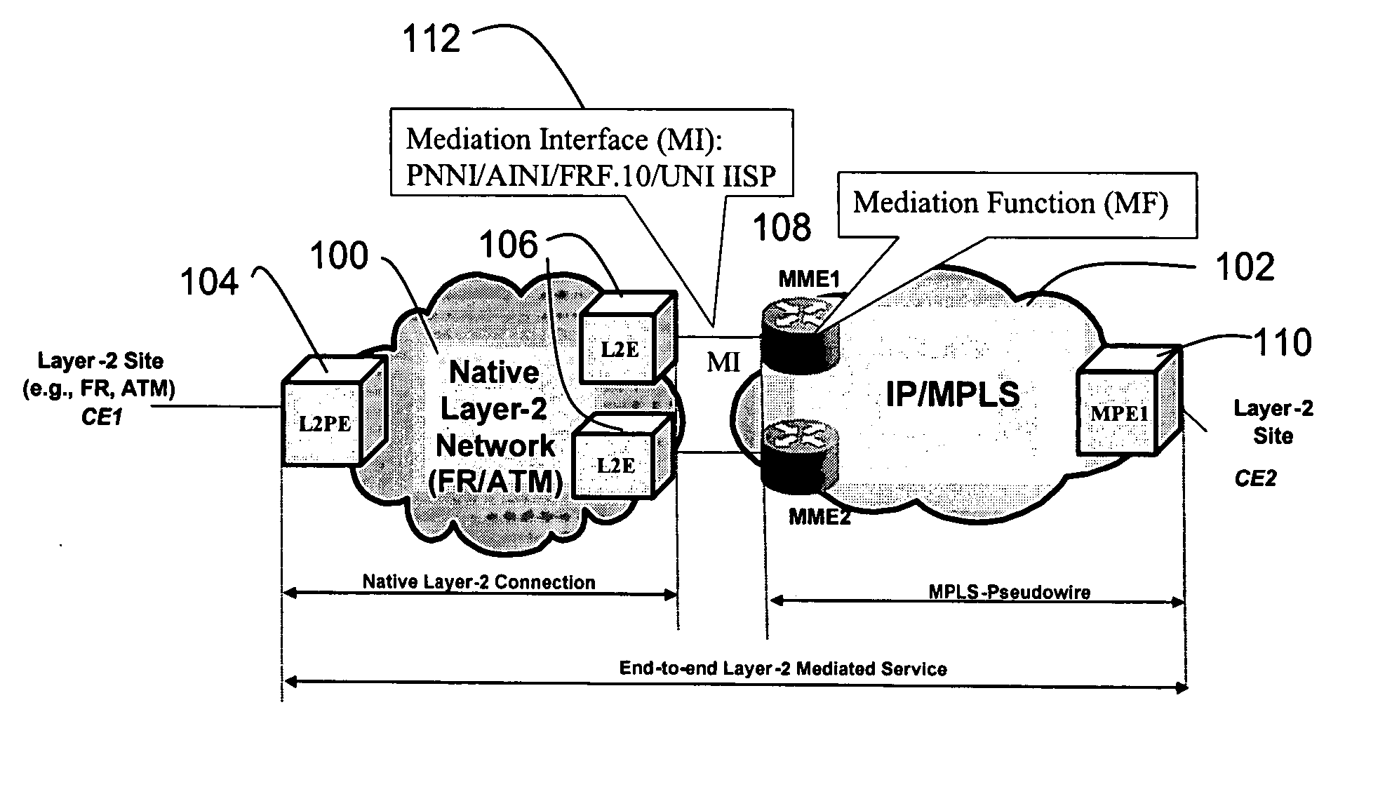
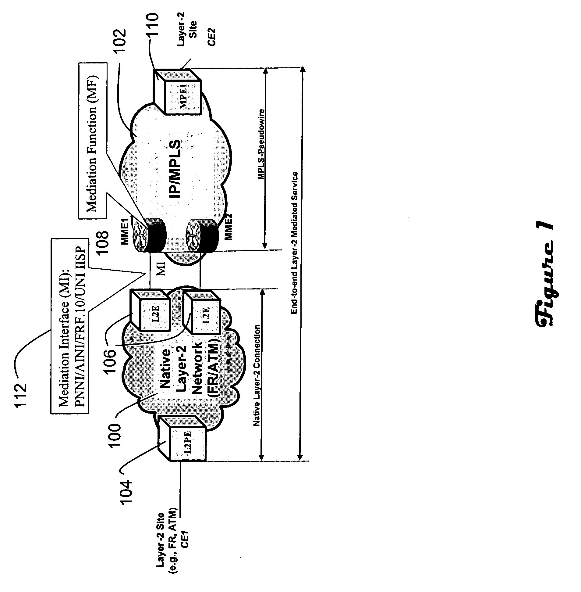
[0023]FIG. 1 illustrates a network reference diagram for Layer-2 to MPLS Service Mediation. The network includes at least one native Layer-2 domain (100) which is in communication with an MPLS domain (102). The native Layer-2 domain employs Frame Relay or ATM, and includes a Layer-2 Provider Edge (“L2PE”) device (104) and Layer-2 Edge (“L2E”) devices (106). The MPLS domain includes MPLS Mediation Edge (“MME”) devices (108) and an MPLS Provider Edge (“MPE”) device (110). The MPE (110) interconnects customer sites that are attached to the MPLS domain (102). The L2Es (106) and MMEs (108) interconnect the Layer-2 domain with the MPLS domain. The MPE and MMEs may, in practice, be the same type of device. The L2PE (104) is a Layer-2 switch which interconnects customer sites that are attached to the Layer-2 domain. The L2Es (106) are Layer-2 devices that interconnect to the MMEs (108) via a Mediation Interface (“MI”) (112). The MI could be based on, for example, FRF.10 / X.76, PNNI, and AINI...


PUM


Abstract

An architecture for providing service mediation in a network having a Layer-2 domain and an MPLS domain includes at least one Layer-2 provider edge device in communication with a first customer site; at least one Layer-2 edge device in communication with the Layer-2 provider edge device; at least one MPLS mediation edge device in communication with the Layer-2 edge device; and at least: one MPLS provider edge device in communication with both the MPLS mediation edge device and a second customer site. An end-to-end connection is established using native Layer-2 signaling, if any, in the Layer-2 domain and PWE3 signaling protocols in the MPLS domain. The MPLS mediation edge device resolves associations between Layer-2 edge devices and MPLS provider edge devices. The service is “mediated” in the sense that native Layer-2 signaling is terminated at the MME, and a new domain, i.e., pseudowire, is established across the MPLS domain.

Description

CROSS-REFERENCE TO RELATED APPLICATIONS [0001] A claim of priority is made to U.S. Provisional Patent Application Ser. No. 60 / 583,381, entitled Layer-2 to MPLS Service Mediation Architecture, filed Jun. 28, 2004, which is incorporated by reference.FIELD OF THE INVENTION [0002] This invention relates generally to the field of network communications, and more particularly to establishing dynamic end-to-end mediated connections from a Layer-2 network to an MPLS network. BACKGROUND OF THE INVENTION [0003] The following documents are incorporated by reference: [0004] [SPVC-IW] Swallow draft “Soft Permanent Virtual Circuit Interworking between PWE3 and ATM”, draft-swallow-pwe3-spvc-iw-00.txt [0005] [PWE3 -CONTROL] Martini, L., et al., “Pseudowire Setup and Maintenance using LDP”, draft-ietf-pwe3-control-protocol-05.txt, December 2003 [0006] [L2VPN-SIG] Rosen, E., Radoaca, V., “Provisioning Models and Endpoint Identifiers in L2VPN Signaling”, draft-ietf-12vpn-signaling-00.txt [0007] [VPN-A...

Claims


Application Information

Patent Timeline
IPC IPC(8): H04J3/16H04L12/46H04L45/02H04L45/50
CPCH04L12/4633H04L29/12009H04L29/12028H04L29/12801H04L29/12877H04L61/604H04L45/50H04L45/502H04L61/103H04L61/106H04L61/6004H04L45/10H04L61/00H04L2101/604H04L2101/64
Inventor OULD-BRAHIM, HAMIDHACHE, ELIZABETHSUGIMOTO, JEFFREYWRIGHT, GREGORY
Owner RPX CLEARINGHOUSE
Learn More