Elevator installation with at least three vertical elevator shafts arranged adjacent to one another and method for operating such a elevator shaft

a technology of vertical elevator shaft and elevator shaft, which is applied in the direction of elevators, instruments, computer control, etc., can solve the problems of limiting the handling capacity and affecting the operation efficiency of the elevator system

a technology of vertical elevator shaft and elevator shaft, which is applied in the direction of elevators, instruments, computer control, etc., can solve the problems of limiting the handling capacity and affecting the operation efficiency of the elevator system

US20060011420A1Inactive Publication Date: 2006-01-19INVENTIO AG

Image

  • Elevator installation with at least three vertical elevator shafts arranged adjacent to one another and method for operating such a elevator shaft
  • Elevator installation with at least three vertical elevator shafts arranged adjacent to one another and method for operating such a elevator shaft
  • Elevator installation with at least three vertical elevator shafts arranged adjacent to one another and method for operating such a elevator shaft

Examples


Embodiment Construction

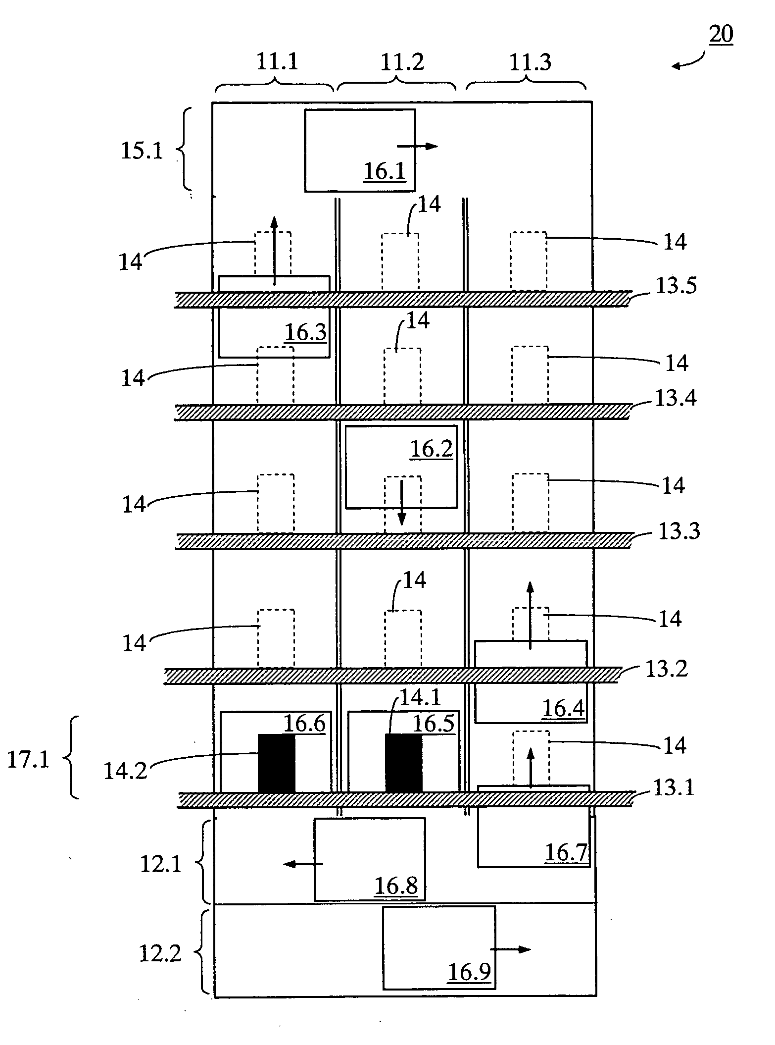
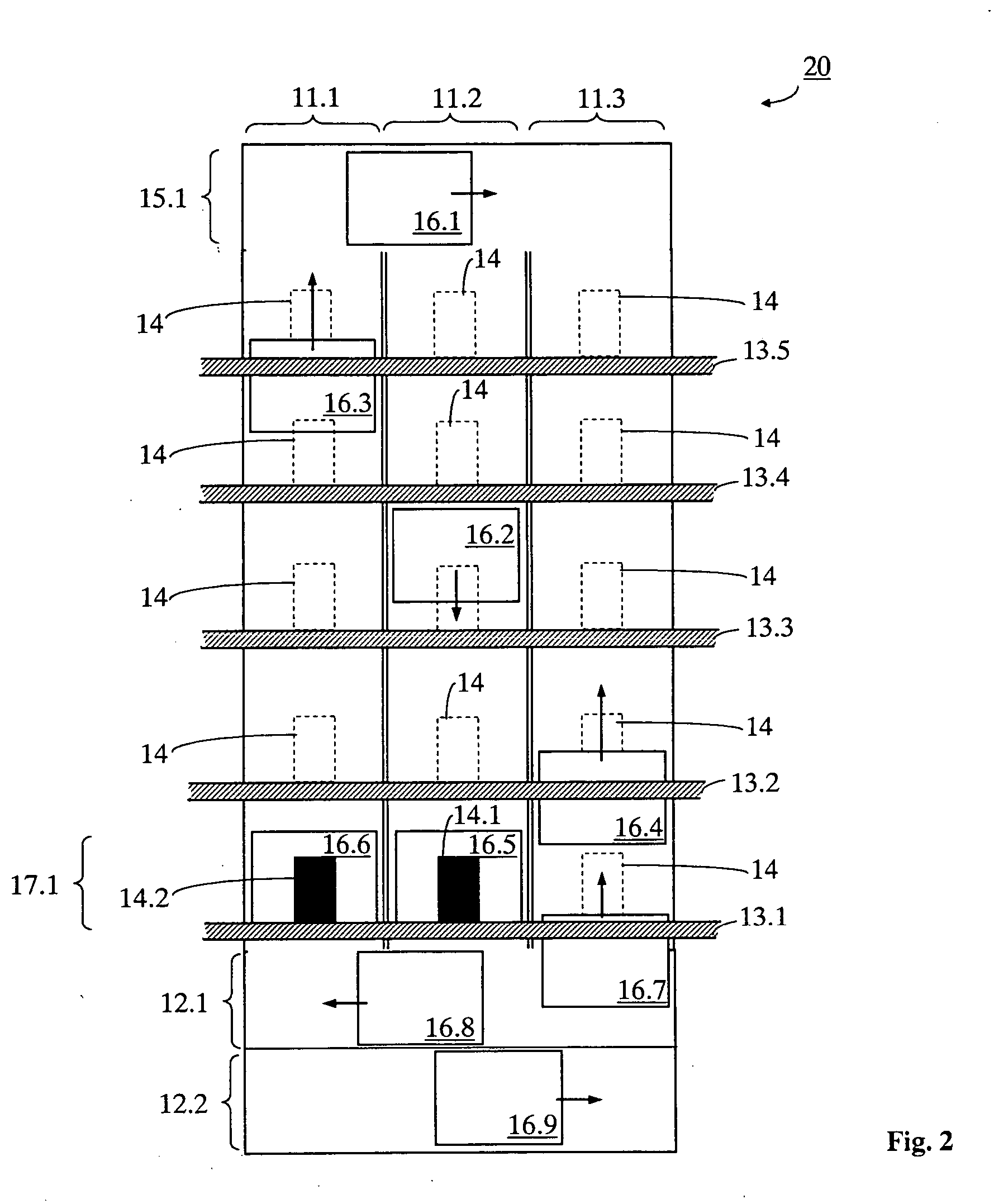
[0023] A first embodiment of the present invention is described in connection with FIG. 2. An elevator installation 20 is shown in a schematic sectional illustration from one side. The elevator installation 20 comprises n=3 vertical elevator shafts 11.1, 11.2 and 11.3 arranged adjacent to one another. The vertical elevator shafts 11.1, 11.2 and 11.3 can, but do not have to be, physically separated from one another. In total, five floors 13.1-13.5 are served. Several individually movable elevator cars 16.1-16.9 are disposed within the elevator shafts 11.1, 11.2 and 11.3. At least two changeover zones 12.1 and 12.2 directly adjacent to one another are provided in the region of a boarding zone 17.1, which enables displacement of the elevator cars 16.1-16.9 between the elevator shafts 11.1, 11.2 and 11.3. In the present example the two changeover zones 12.1, 12.2 lie one directly above the other. The lowermost floor, which is denoted in FIG. 2 by 13.1, is regarded as the boarding zone 1...


PUM


Abstract

An elevator installation has at least three vertical elevator shafts arranged adjacent to one another, at least one boarding zone and a plurality of individually movable elevator cars. At least two directly adjacent changeover zones are provided in the region of the boarding zone and enable horizontal displacement of the elevator cars between the elevator shafts.

Description

BACKGROUND OF THE INVENTION [0001] The present invention relates to elevator installations with vertical elevator shafts arranged adjacent to one another and individually movable elevator cars able to carry out a shaft change, as well as to a method of operating such elevator installations. [0002] Every elevator installation requires a certain proportion of space in a building depending on the traffic volume. The larger the traffic volume and the higher the building, the more space the elevator installation needs in relation to usable area (net useful area) of the building. The performance of an elevator installation can be expressed by the so-called handling capacity. The handling capacity indicates how many persons can be transported per minute in the case of high traffic volume, for example at the beginning of a working day in an office building. [0003] It is therefore of concern to minimize the space requirement of an elevator installation. This is achieved by measures which all...

Claims


Application Information

Patent Timeline
19 Jan 2006
Publication
US20060011420A1
IPC
B66B1/18
CPC
B66B9/00; B66B9/02; B66B9/003
Inventors
DUENSER, THOMAS; ANGST, PHILIPP