De-icing cable jig construction

a cable jig and de-icing technology, applied in the field of de-icing cable jig construction, can solve the problems of ice dams being an ever present danger, uniform in their failure to provide simple, efficient and practical,

Inactive Publication Date: 2006-01-19
GRAVES WILLIAM LOUIS
View PDF6 Cites 2 Cited by
  • Summary
  • Abstract
  • Description
  • Claims
  • Application Information

AI Technical Summary

Benefits of technology

[0011] Briefly stated, the de-icing cable jig construction that forms the basis of the present invention is specifi

Problems solved by technology

While all of the aforementioned prior art constructions are more than adequate for the basic purpose and function for which they have been specifically designed, they are uniformly deficient with respect to their failure to provide a simple, efficient, and practical de-icing arrangement that is adapted to be secured to existi

Method used


Image

  • De-icing cable jig construction
  • De-icing cable jig construction
  • De-icing cable jig construction

Examples


Embodiment Construction

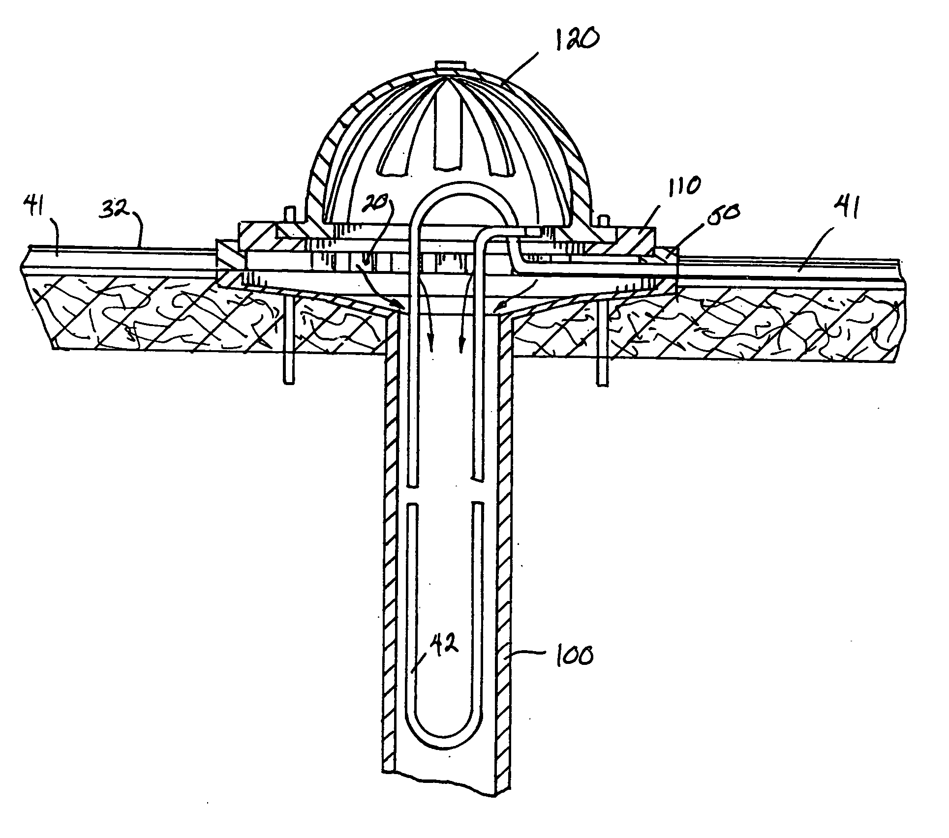
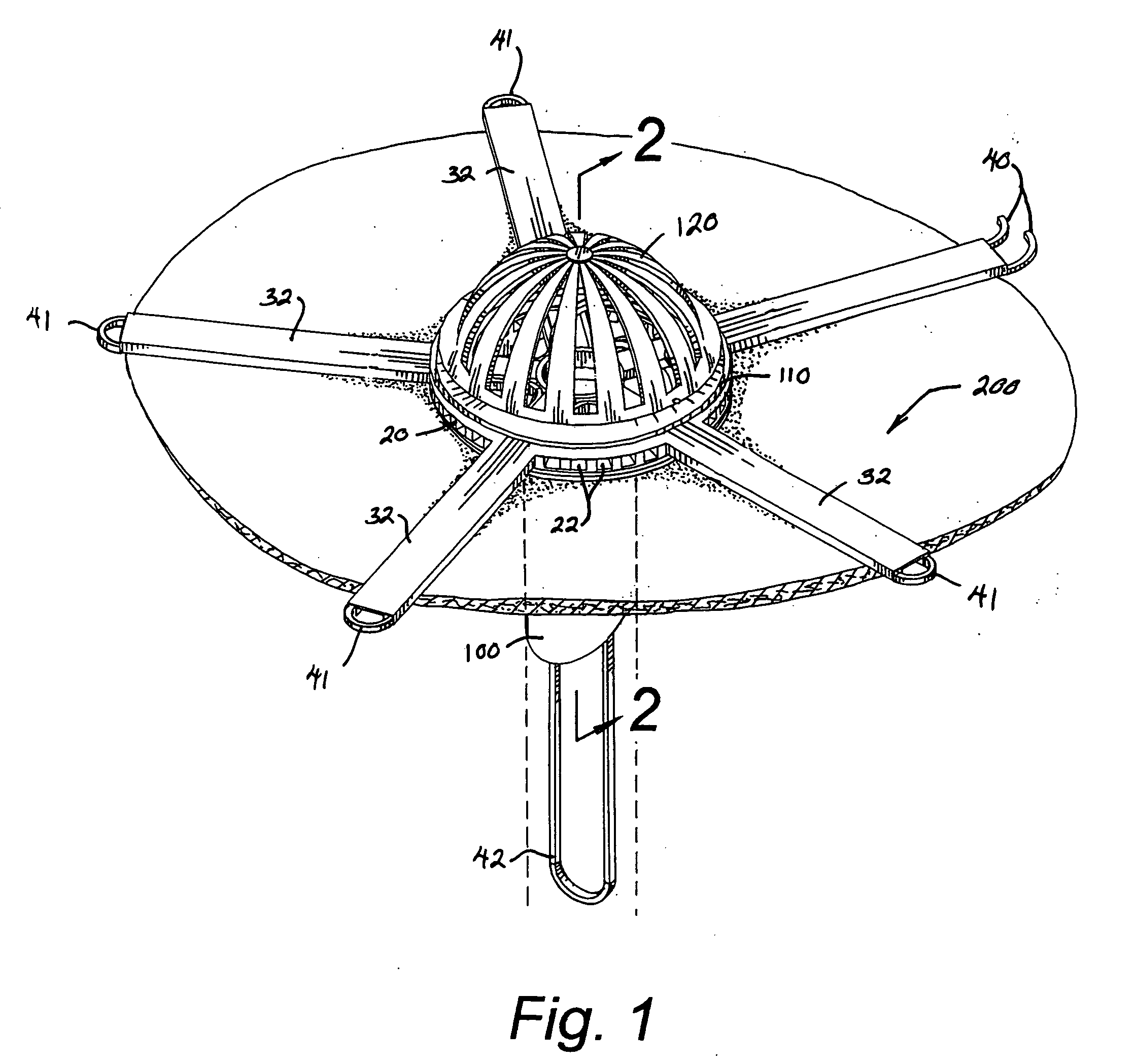
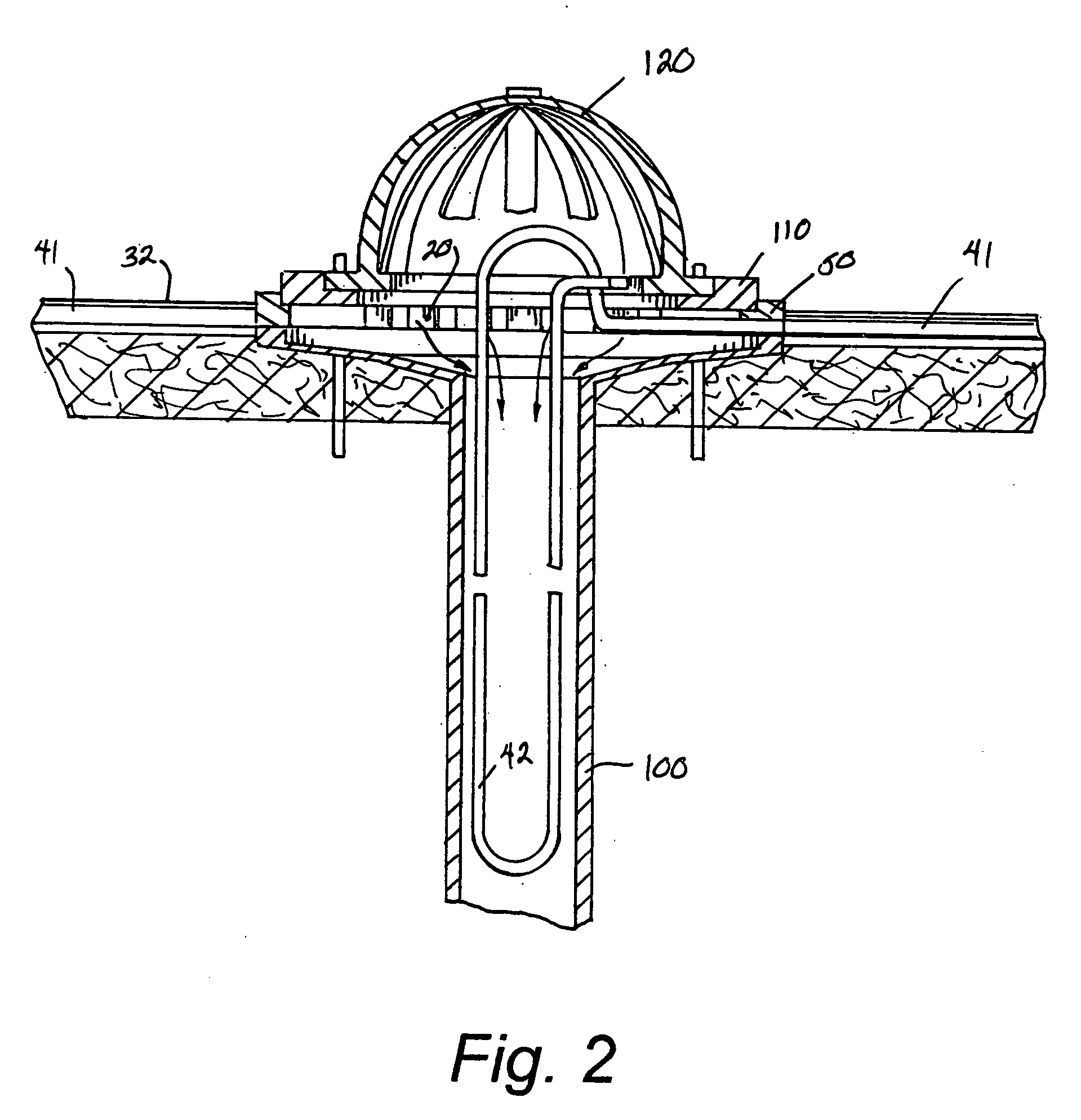
[0023] As can be seen by reference to the drawings, and in particularly to FIG. 3, the de-icing cable jig construction that forms the basis of the present invention is designated generally by the reference number 10. The construction 10 comprises in general a base plate unit 11, a cable track unit 12 and a heating cable unit 13 employed in combination with a conventional floating membrane roof drain 100, a conventional clamping collar 110 and a conventional domed strainer 120. The aforementioned units will now be described in seriatim fashion.

[0024] As can best be seen by reference to FIG. 7, the base plate unit 11 comprises a circular base plate member 20 provided with a first plurality of enlarged track arm recesses 21 and a second plurality of drainage slots 22 arranged in a radial fashion around an enlarged central base plate opening 23.

[0025] In addition, as can be seen by reference to FIGS. 4, 6 and 7, the cable track unit 12 includes a hollow hub member 30 provided with a p...


PUM


Abstract

A de-icing cable jig construction (10) for a floating membrane roof drain (100) provided with a clamping collar (110) and a domed strainer (120) wherein, the jig construction (10) includes a base plate member (20) provided with drainage slots (22) and track arm recesses (21) that are adapted to receive a plurality of track arms (31) projecting radially outwardly from a hub member (30) wherein, the track arms (31) are provided with sleeve elements (32) that define track channels for an elongated length of heating cable (40) arranged into horizontal heating cable loops (41).

Description

CROSS REFERENCE TO RELATED APPLICATIONS [0001] This invention was the subject matter of Document Disclosure Program Registration Number 546,767, filed in the United States Patent and Trademark Office on Feb. 13, 2004. STATEMENT REGARDING FEDERALLY SPONSORED RESEARCH OR DEVELOPMENT [0002] Not applicable. REFERENCE TO MICROFICHE APPENDIX [0003] Not applicable. BACKGROUND OF THE INVENTION [0004] 1. Field of the Invention [0005] The present invention relates to the field of roof de-icing arrangements in general and in particular to a de-icing apparatus that can be retrofitted onto existing roof drain constructions. [0006] 2. Description of Related Art [0007] As can be seen by reference to the following U.S. Pat. Nos. 3,784,783; 3,816,687; 6,225,600; 5,960,590; and, 4,333,444, the prior art is replete with myriad and diverse snow and ice melting arrangements for roofs, gutters, drains and the like. [0008] While all of the aforementioned prior art constructions are more than adequate for ...

Claims


Application Information

Patent Timeline
IPC IPC(8): H05B1/00
CPCE04D2013/0418E04D13/0409
Inventor GRAVES, WILLIAM LOUIS
Owner GRAVES WILLIAM LOUIS
Why Eureka
Try Eureka